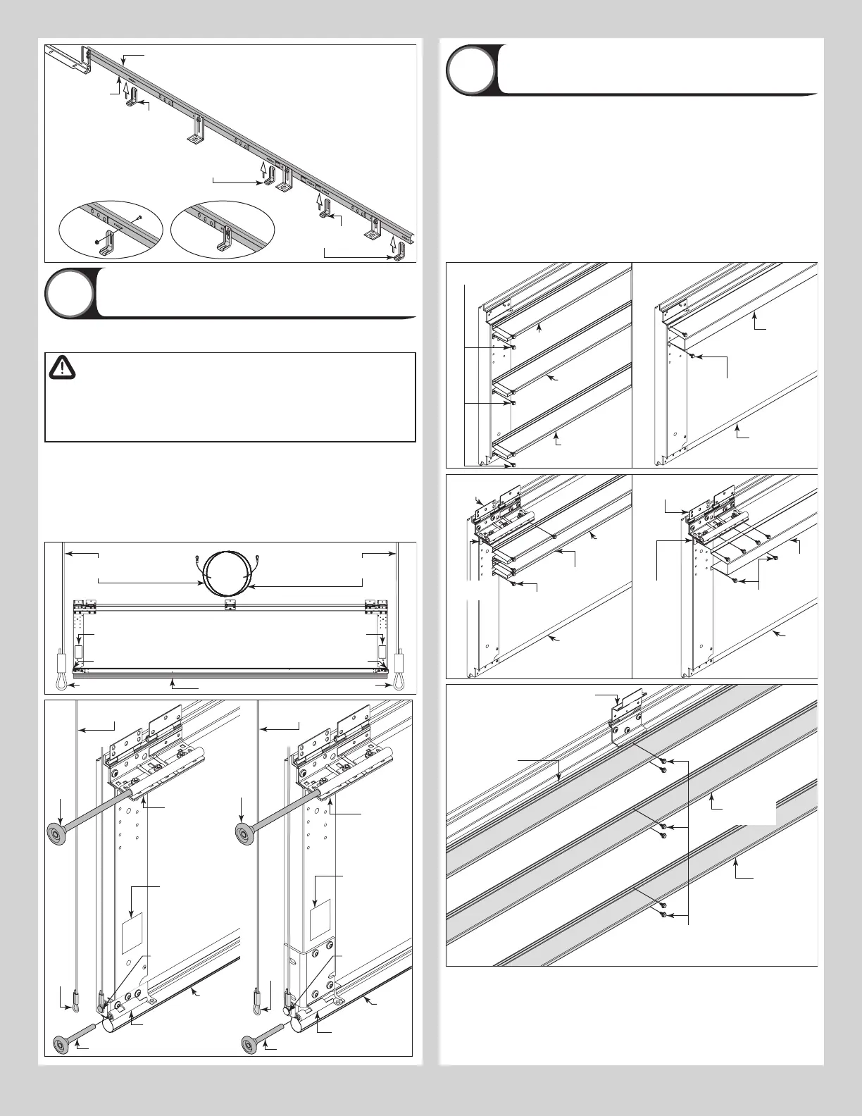
vertical track
NOTE: Loosely fasten
components together.
Repeat the same process
for the right hand side.
Typical left hand
vertical track
assembly
Left hand windload
jamb bracket
NOTE: Measure the length of the vertical tracks.
Using the Jamb Bracket Schedule (shown on the
Windload Specification Sheet included in the
hardware box), determine the placement of the
windload jamb brackets for your door height.
Left hand
windload jamb
bracket
Left hand
windload jamb
bracket
Attaching Counterbalance Lift Cables and
Track Rollers
4
NOTE: Refer to door section identification, located in the pre-installation section of this
manual or refer to Breakdown Of Parts.
WARNING
ENSURE TIGHT FIT OF CABLE LOOP OVER MILFORD PIN TO PREVENT
COUNTERBALANCE LIFT CABLE FROM COMING OFF THE PIN, WHICH
COULD ALLOW THE DOOR TO FALL AND RESULT IN SEVERE OR FATAL
INJURY.
Uncoil the counterbalance lift cables. Starting on the left hand side, place the left hand cable
loop on the left hand milford pin of the bottom corner bracket. Insert a short stem track roller
into the bottom corner bracket and another into the roller slide at the top of the bottom sec-
tion. Repeat for other side.
NOTE: Larger doors will use long stem track rollers with double graduated end hinges.
NOTE: Verify bottom weather seal is aligned with bottom section. If there is more than 1/2”
excess weather seal on either side, trim weather seal even with bottom section.
Counterbalance
lift cable
Counterbalance
lift cable
Cable loop
Bottom section
Cable loop
Bottom corner
bracket warning label
Bottom corner
bracket warning label
Milford pin Milford pin
Double
graduated
end hinge
(Hinge tube)
lift cable
Long
stem
track
roller
Bottom
weather
seal
Bottom
section
Milford
pin
Cable
loop
Milford
pin
Bottom corner
bracket
Short stem track roller
Bottom
corner
bracket
warning
label
Double
graduated
end hinge
(Hinge tube)
lift cable
Long
stem
track
roller
Bottom
weather
seal
Cable
loop
Bottom corner
bracket
Short stem track roller
Bottom
section
Bottom
corner
bracket
warning
label
Attaching Strut(s) To Section
5
NOTE: Refer to door section identification, located in the pre-installation section of this
manual or refer to Breakdown Of Parts.
NOTE: Refer to Package Contents / Breakdown Of Parts, to determine if strut(s) and or hinge
bracket(s) are required to be installed.
NOTE: The illustrations below are only meant to be used as an aid and does not replace the
Windload Specification Sheet that was provided with your door.
NOTE: Some struts may be factory installed.
Depending on the size of your door, one or more sections may require a strut and hinge
brackets. Using sawhorses, lay a section on a flat smooth surface. Refer to the Windload
Specification Sheet for the strutting schedule and the required number of 1/4” - 20 x 7/8”
self drilling screws to be used to secure the components to the section. Repeat the same
process for the other sections.
Typical
section
4” Strut
1/4”-20 x 7/8”
Self drilling screws
Typical
section
3” Strut
1/4”-20 x 7/8”
Self drilling screws
3” Strut
3” Strut
hinge
Typical
section
Reinforcing
bracket
3” Strut
1/4”-20 x 7/8”
Self drilling screws
Graduated end
hinge
Typical
section
Reinforcing
bracket
4” Strut
1/4”-20 x 7/8”
Self drilling screws
3” Strut (if applicable)
hinge(s)
Strut at the
bottom of the
section
1/4”-20 x 7/8”
Self drilling screws
Strut at the
middle of the
section
Strut at the top
of the section
8