26
SECTION IV
SERVICE
Caution: Make sure the manual gas valves and main electrical power to the burner are turned off before opening
burner or removing any parts for service.
A. BURNER HEAD AND ELECTRODE/SENSOR ASSEMBLY
The burner head, electrode, sensor probe, orifice housing and housing cover are part of the burner head assembly which
can be removed as one unit (Figure 16).
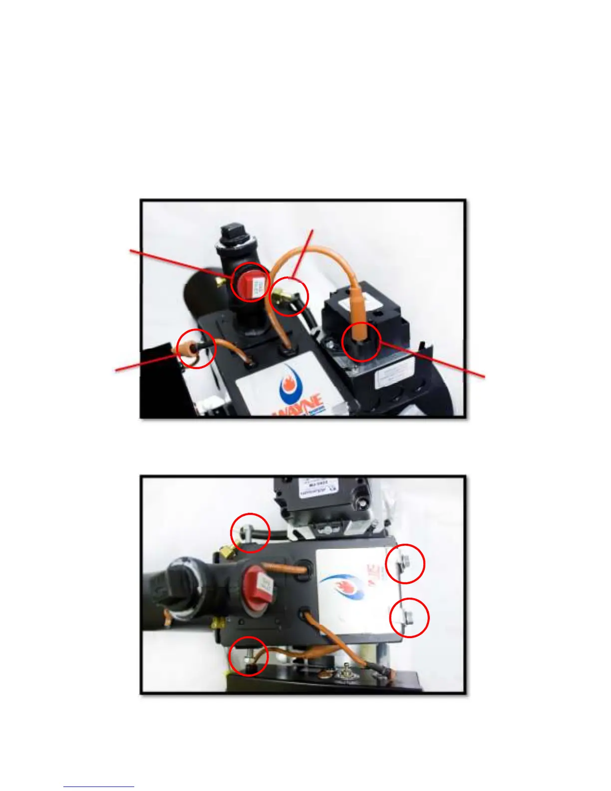
1. Disconnect the gas train from the burner inlet, also disconnect the flame sensor lead wire, ignition transformer
wire, and the clear tubing located on the brass hose barb on the top of the housing (Figure 13).
Figure 13
2. Remove the four 1/2” bolts that attach the cover/manifold assembly to the burner (Figure 14).
Figure 14
Gas
Inlet
Clear
Tube
Ignition
Transformer
Wire
Flame Sensor
Lead Wire