27
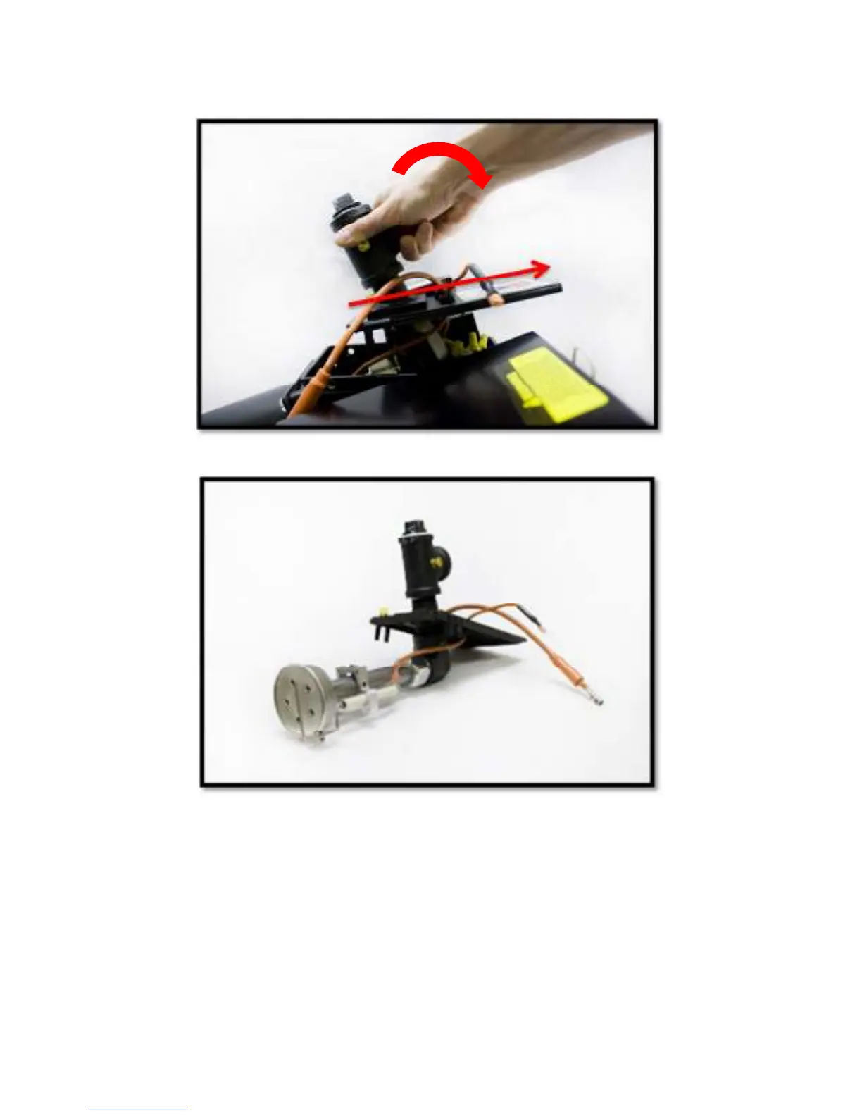
3. To begin removing gas train assembly, gently lift up rear of housing cover while pulling back. Rotate the assembly
about 90 degrees toward the left side of the burner and gently extract burner head and electrode/sensor assembly
out of opening in housing taking extreme care to not dislocate or damage electrode or sensor probe (Figure 15).
Figure 15
Figure 16
4. When servicing, clean burner head ports, electrodes and sensor probe. Inspect the sensor probe and electrode
wires and porcelain insulators carefully for hairline cracks which might provide an electrical leak path that could
short out the ignition spark or flame signal.
5. Examine the electrode and sensor probe for any serious corrosion or deterioration of metal at the tips. Check for
proper dimensional settings of the sensor probe and electrode (See Figure 1). Adjust and/or replace these
assemblies as necessary. Make sure that the ignition and sensor probe wires go to the correct electrodes and the
ignition wire boot is in place over the electrode porcelain.
6. Make sure that the burner tube end is properly positioned in the combustion chamber entry. It must be set 1/2”
(12.7mm) short of the inside face of the combustion chamber.