28
B. AIR PROVING SWITCH
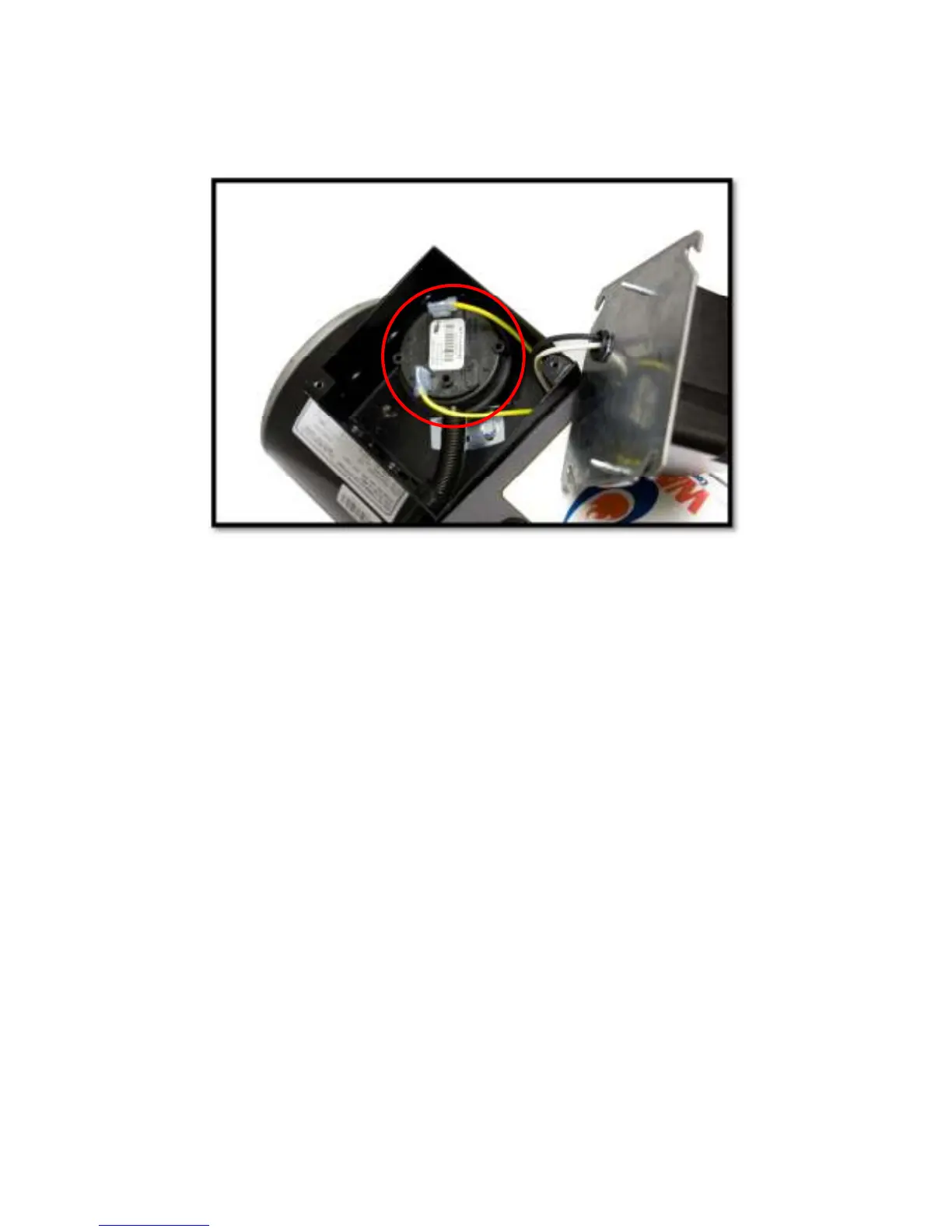
The air proving switch has a black plastic top and grey bottom and is mounted inside the junction box on the right side of
the burner housing (Figure 17). A clear plastic tube is connected to the barbed fitting on the pressure switch while the
other end is connected to a brass barbed fitting on the cover/manifold assembly. The plastic tube allows pressurized air
from the blower housing to travel to the pressure switch causing diaphragm contacts to close thus completing the circuit.
Figure 17
The function of the air proving switch is to ensure sufficient combustion air is being developed by the blower motor and
blower wheel. Should the blower motor fail or the blower wheel malfunction, the burner gas valve will shut off.
1. The air proving switch should never require maintenance. However, should nuisance lockouts occur, the pressure
switch can be checked. This is done by disconnecting the 24V leads from the Air Proving switch and jumpering the
leads together. If the burner functions correctly, the switch needs to be replaced.
WARNING: If a jumper is used to check the switch it must be removed or an unsafe condition can occur resulting in
property damage, personal injury or death.
2. As mentioned above, the switch should never require maintenance. However a pinched tube will shut off the flow of
pressurized air to the diaphragm creating a failure similar to a bad air proving switch. Always check to ensure that the
clear tubing is not pinched. Make sure the spring cover is reinstalled over the tube.
WARNING: For proper air switch operation, the burner must be mounted in the horizontal position. If it is necessary to
mount the burner in a vertical position, the air switch must be repositioned to the horizontal. Contact Wayne Combustion
Systems for details.