EasyManua.ls Logo

Wayne HS - User Manual

Wayne HS
22 pages
Print Icon
To Next Page IconTo Next Page
Loading...
WAYNE COMBUSTION SYSTEMS
801 GLASGOW AVE.
FORT WAYNE, IN 46803
PHONE: (260) 425-9200
(800) 443-4625
FAX: (260) 424-0904
HS
Oil
Burner
Manual: 21663
Revision 15
Publication Date: 7/26/2011
Firing Capacity:
70,000 – 420,000 BTU/HR
0.50 – 3.00 GPH
(additional hardware required to fire above 2.50 GPH)
Electrical:
Power Supply..............115V / 60Hz / 1-Phase
Motor...............................................3450 RPM
Ignition...................................10,000V / 23mA
Fuels:
No.1 or No.2 heating oil, diesel, B5, kerosene,
or JP8 Jet Fuel
Dimensions (Standard):
Height.....................................................12 ½”
Width......................................................12 ⅞”
Depth........................................................7 ¾”
Center Line of Tube to Floor.........................7”
INSTALLATION OF BURNER
INSTALLATION OF THE BURNER MUST BE DONE BY A QUALIFIED INSTALLER IN ACCORDANCE WITH REGULATIONS OF THE NATIONAL
FIRE PROTECTION STANDARD FOR OIL-BURNING EQUIPMENT, NFPA NO. 31, AND IN COMPLETE ACCORDANCE WITH ALL LOCAL CODES
AND AUTHORITIES HAVING JURISDICTION.
INCORRECT INSTALLATION, ADJUSTMENT, OR MISUSE OF THIS BURNER COULD RESULT IN DEATH, SEVERE
PERSONAL INJURY, OR SUBSTANTIAL PROPERTY DAMAGE AND WILL VOID THE WARRANTY.
A QUALIFIED INSTALLER IS THE PERSON WHO IS RESPONSIBLE FOR THE INSTALLATION AND ADJUSTMENT OF THE EQUIPMENT AND
WHO IS LICENSED TO INSTALL OIL-BURNING EQUIPMENT IN ACCORDANCE WITH ALL CODES AND ORDINANCES.
THESE INSTRUCTIONS SHOULD BE AFFIXED TO THE BURNER
OR ADJACENT TO THE HEATING APPLIANCE.
Question and Answer IconNeed help?

Do you have a question about the Wayne HS and is the answer not in the manual?

Summary

Wayne HS Oil Burner Introduction

Wayne Combustion Systems Company Details

Company address, phone, and fax information for Wayne Combustion Systems.

HS Oil Burner Key Specifications

Firing capacity, electrical requirements, fuel types, and dimensions of the HS oil burner.

Critical Installation Safety Warnings

DANGER and WARNING statements regarding burner installation and operation.

General Information and Safety

Homeowner Guidance and Service

Guidance for homeowners on burner operation and recommended service.

Understanding Hazard Symbols

Definitions and explanations of DANGER, WARNING, CAUTION, and NOTICE symbols.

Product General Specifications

Detailed specifications including firing rate, fuels, electrical, and dimensions.

Essential Safety Precautions

Critical safety advice on electrical shock, overheating, fuel use, and installation risks.

Prepare Installation Site

Site Preparation and General Notes

Ensuring adequate space, clean flue passages, and proper chimney setup.

Combustion Chamber Guidelines

Requirements for combustion chamber type, size, and installation details.

Fuel System and Air Supply Preparation

Fuel Pump and Line Installation

Guidelines for fuel pump operation, fuel lines, and filter requirements.

Fuel Tank and Air Requirements

Regulations for fuel tanks and air supply for combustion.

Chimney and Draft Regulator Setup

Recommendations for chimney design and draft regulator installation.

Prepare Burner Components

Gun Assembly Removal Procedure

Step-by-step instructions for safely removing the gun assembly.

Nozzle Installation and Handling

Proper procedures for installing and handling burner nozzles.

Burner Component Adjustments

Electrode Settings Adjustment

Correct spacing and alignment for burner electrodes for reliable ignition.

Burner Assembly and Wiring

Gun Assembly Installation

Instructions for correctly installing the gun assembly into the burner.

Air Cone Position Calibration

Procedure to calibrate the air cone position for optimal combustion.

Wiring Diagrams and Compliance

Wiring guidelines and compliance with electrical codes for burner installation.

Starting Procedure

Initial Burner Startup Steps

Steps to follow for the initial startup of the oil burner.

Fine-Tuning Combustion Settings

Adjusting air and fuel for optimal combustion efficiency and low smoke.

Setting Combustion Efficiency and Final Checks

Adjusting for Optimal Combustion

Using CO2 and smoke readings to achieve efficient combustion.

Final Inspection and System Checks

Verifying all settings, controls, and connections are correct after adjustments.

Burner Maintenance

Scheduled Maintenance Tasks

Routine maintenance including motor oiling, filter, and nozzle replacement.

Blower Wheel Replacement Guidelines

Procedure and spacing checks for blower wheel and motor replacement.

Suntec Pump Installation Details

Information on mounting positions, vacuum checks, and pump installation.

Pressure Check and Solenoid Wiring

Performing Pressure Checks

Correct procedures for checking pump and nozzle pressures.

Solenoid Oil Valve Wiring

Wiring diagrams for the solenoid oil valve and its connection.

Fuel Piping Systems

One-Pipe System (Model A)

Instructions for setting up a one-pipe fuel system, including bleeding.

Two-Pipe System (Models A & B)

Guidelines for installing two-pipe fuel systems with bypass plug.

Strainer and Nozzle Selection

Two-Stage, Two-Pipe Line Lengths

Table detailing maximum line lengths for two-stage, two-pipe systems.

Choosing the Correct Nozzle

Guidance on selecting nozzle types, sizes, and spray angles.

Spray Angle Recommendations

Nozzle Flow Rate Effects

Table showing how pressure affects nozzle flow rates.

Matching Spray Angle to Chamber

Suggested spray angles for different combustion chamber types and sizes.

Oil Primary Specifications

101343-SER Control Features

Features of the 101343-SER oil primary control, including recycle and lockout.

Diagnostic LED and Cad Cell Resistance

Interpreting diagnostic LED states and checking cad cell resistance.

Technical Specifications

Timing and Electrical Ratings

Timing parameters, input/output electrical ratings, and wire color codes.

Environmental and Approval Ratings

Operating ambient temperature, humidity, and agency approvals.

Burner Replacement Parts

HS Model Part Breakdown

Illustrated parts list for the HS model burner with part numbers.

Gun Assembly Components

Specific parts breakdown for the gun assembly.

Wayne Fuel Blend Safety Information

Kerosene Handling Precautions

Safety precautions for handling kerosene, including vapor hazards.

First Aid Measures for Exposure

First aid procedures for inhalation, skin, eye contact, and ingestion.

Wayne Limited Warranties

Warranty Coverage and Conditions

Terms and conditions for oil and gas burner limited warranties.

Warranty Exclusions and Limitations

Limitations, exclusions, and implied warranty disclaimers for burner products.

Overview

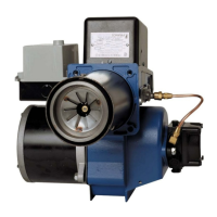
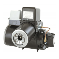
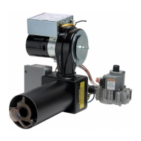
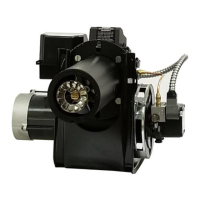
The device described in the manual is the Wayne HS Oil Burner, a combustion system designed for residential oil-fired boilers, forced-air furnaces, and water heaters. It is manufactured by Wayne Combustion Systems.

Function Description

The Wayne HS Oil Burner is designed to efficiently burn heating oil to produce heat. It operates by atomizing fuel oil, mixing it with combustion air, and igniting the mixture to create a stable flame within a combustion chamber. The system includes a fuel pump, motor, ignition system, and controls to manage the combustion process. It can be used with both hydronic and forced-air heating systems. The primary control, specifically the 101343-SER Electronic Oil Primary, manages fuel oil delivery, senses flame presence, controls ignition spark (intermittent or interrupted), and signals a remote alarm circuit if a lockout occurs.

Important Technical Specifications

Firing Capacity:

  • BTU/HR: 70,000 – 420,000 BTU/HR
  • GPH (Gallons Per Hour): 0.50 – 3.00 GPH (additional hardware required for firing above 2.50 GPH)

Fuels:

  • No. 1 or No. 2 heating oil
  • Diesel
  • B5 blend
  • Kerosene
  • JP8 Jet Fuel
  • Restrictions: NEVER burn garbage, refuse, waste, crankcase oil, or gasoline.

Electrical:

  • Power Supply: 115V / 60Hz / 1-Phase
  • Motor: 3450 RPM, N.E.M.A. Flange, Auto Overload Protection
  • Ignition: 10,000V / 23mA secondary, Continuous Duty-Shielded Interrupted

Dimensions (Standard):

  • Height: 12 1½"
  • Width: 12 7/8"
  • Depth: 7 3/4"
  • Center Line of Tube to Floor: 7"

Fuel Pump:

  • Type: Suntec, single-stage 3450 RPM for single-pipe installations.
  • Vacuum Limits: Model "A" pump: max 6" Hg (single pipe), 12" Hg (two pipe). Model "B" pump: max 17" Hg.
  • Cutoff Pressure: Average 80 psig.
  • Inlet Line Pressure: Pressurized or gravity feed installations must not exceed 10 psi on inlet or return line at the pump to prevent shaft seal damage.

Oil Primary (101343-SER Electronic Oil Primary):

  • Timing:
    • Safe Start Check: 5 seconds (approx.)
    • Lockout: 15, 30, or 45 seconds (factory-programmed); Wayne Lockout Timing: 15 seconds
    • Recycle: 60 seconds (fixed)
    • Ignition Carryover: 10 seconds (fixed)
  • Electrical Ratings:
    • Voltage: 102 to 132 Vac, 120 Vac nominal
    • Current: 100 mA plus burner motor loads
    • Frequency: 60 Hz
    • Burner Relay Contacts: 120 Vac, 10 FLA, 60 LRA
    • Thermostat Current Available: 100 mA
    • EnviraCOM™ Current Available: 150 mA
  • Environmental Ratings:
    • Operating Ambient Temperature: -40°F to +150°F (-40°C to +66°C)
    • Shipping Temperature: -20°F to +150°F (-29°C to +66°C)
    • Humidity: 90% relative humidity at 95°F (35°C), non-condensing
  • Cad Cell Resistance:
    • Less than 400 Ohms (1 flash)
    • 400-800 Ohms (2 flashes)
    • 800-1600 Ohms (3 flashes)
    • 1600-5000 Ohms (4 flashes)

Usage Features

Installation:

  • Requires installation by a qualified, licensed technician in accordance with NFPA No. 31 and all local codes.
  • Adequate space for service and maintenance must be provided.
  • Combustion chamber, flue gas passages, and heat absorbing surfaces must be clean and tightly sealed to prevent air infiltration and ensure efficiency.
  • Chimney must be properly sized and maintained; a draft regulator is recommended.
  • Combustion air supply must be adequate, especially in confined spaces or unusually tight constructions.
  • Nozzle Installation: Requires careful handling to avoid damaging the nozzle face, filter, or electrodes. Electrode settings must be precisely spaced from the nozzle face (5/16" height, 1/8" gap, 1/16" from nozzle face).
  • Air Cone Position Calibration: Necessary if gun assembly components have been replaced.
  • Wiring: Must comply with National Electric Code and local ordinances. Supports intermittent and interrupted ignition wiring.
  • Fuel Lines: Heavy wall copper tubing recommended. All connections must be airtight, and flared fittings are preferred. Shutoff valves and an adequate oil filter are required.
  • Fuel Tanks: Must comply with local codes, be free of water and sludge, and existing piping should be clean or replaced.

Starting Procedure:

  • Initial setup involves adjusting the primary air damper and gun assembly based on the desired GPH firing rate.
  • The burner is equipped with an Air Cone to fire 0.50 to 2.50 GPH.
  • Pump priming is necessary for new installations or after running dry.
  • Final Adjustments: Involves using a combustion test kit to achieve optimal CO2 and smoke levels, and checking stack temperature.
  • Combustion Efficiency Setting: Involves selecting the firing rate, installing the proper nozzle and baffle, adjusting the gun, and tuning the combustion damper for a yellow flame.
  • Final Checks: Ensures all screws are locked, and controls are adjusted per manufacturer instructions.

Safety Features:

  • Hazard Definitions: Clearly outlines DANGER (death, serious injury, property damage), WARNING (personal injury, property damage), and CAUTION (personal injury, property damage) notices.
  • Electrical Shock Hazard: High voltages present; requires proper grounding, a ground fault interrupter, turning off power before servicing, and avoiding water spray.
  • Overheating Hazard: Instructions for what to do if overheating occurs (shut off manual oil valve, do NOT shut off control switch to pump/blower).
  • Explosion Hazard: Explicitly warns against using gasoline as fuel.
  • Flammable Vapors: Caution against storing or using flammable vapors near the appliance.
  • Limited Recycle: The 101343-SER primary control limits recycle trials to three per heat call; locks out if flame is lost three times.
  • Limited Reset (Restricted Mode): Control can only be reset three times to limit unburned oil accumulation. Reset count returns to zero after a successful heat call.
  • Lockout Mode: The primary control enters lockout mode under specific conditions (e.g., flame detected during valve-on delay, no flame during Trial for Ignition, flame lost three times, flame detected during burner motor-off delay).

Maintenance Features

Scheduled Maintenance (Annual Recommendation):

  • Oiling Motor: Sleeve bearing motors require 6 drops of SAE 20 oil once a year; ball-bearing motors do not require oiling.
  • Oil Filter: Replace the cartridge once a year to prevent contamination and clogging of the fuel pump and nozzle.
  • Nozzle: Change the nozzle at least once a year before the heating season. Handle carefully to avoid contamination or damage to the spray pattern.
  • Fan & Blower Housing: Keep clean of dirt and lint. Check fan blades from above by opening the transformer and off-cycle damper.
  • Electrode Settings: Check annually for proper spacing and replace if worn, oil-soaked, or cracked. Ensure electric power is off before inspection.
  • Blower Wheel Replacement: If replaced, the spacing between the blower and motor must be 9/64" (0.140") to ensure proper function.

Diagnostic Features:

  • Diagnostic LED: The 101343-SER primary control has an LED that indicates:
    • On: Flame present
    • Off: No flame
    • Two seconds on, two seconds off: Recycle
    • 1/2 second on, 1/2 second off: Lockout
  • Cad Cell Resistance Check: Can be checked without an ohmmeter by pressing and releasing the reset button during run mode; the resulting LED flashes indicate resistance levels.
  • Data Port: Allows for networking and adding upgrade modules.
  • Pump Priming Cycle: A routine to purge air from oil lines and filters, initiated by pressing the reset button within 15 seconds of motor start. Extends lockout timing to four minutes for this cycle.

Parts and Service:

  • Replacement parts should be manufacturer-recommended.
  • When ordering parts or communicating, specify burner model and serial numbers.
  • A "Burner / Appliance Service Log" is provided for recording service dates, contractor licenses, and actions performed.
  • Limited Warranty: Covers defects in material and workmanship for 36 months from the date of manufacture for oil burners (18 months for gas burners). Requires proper installation by a qualified technician. Warranty covers repair or replacement of defective components at Wayne's option but excludes labor costs.

Wayne HS Specifications

General IconGeneral
BrandWayne
ModelHS
CategoryBurner
LanguageEnglish

Related product manuals