M
mackenzieyangSep 7, 2025
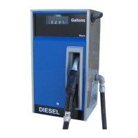
What does fault code 02 mean on a Wayne Vista Dispenser?
- JJoseph DeleonSep 7, 2025
Fault code 02 may indicate defective wiring. Check the two wires in the DEM that are connected to the two-wire connector at the lower left corner of the DEM (where the push-to-start switch is normally connected). Repair or replace the wiring as necessary. If the wiring is not the issue, the lighted cash/credit interface board or the computer itself might be defective. Replace the cash/credit interface board or the computer as needed.