SECTION 12: DAMPERS
31
12.1 Discharge Damper
Discharge dampers are shipped loose. Discharge dampers are designed to be mounted downstream of the
air handler in ductwork. A qualified contractor/installer must make appropriate allowances for duct
connections.
To install the discharge damper on an interior wall, drill holes every 8" (20.5 cm) in the flanges on all four
sides of the discharge damper to accommodate lag bolts (provided by others).
Discharge dampers are not recommended to be mounted directly to the air handler.
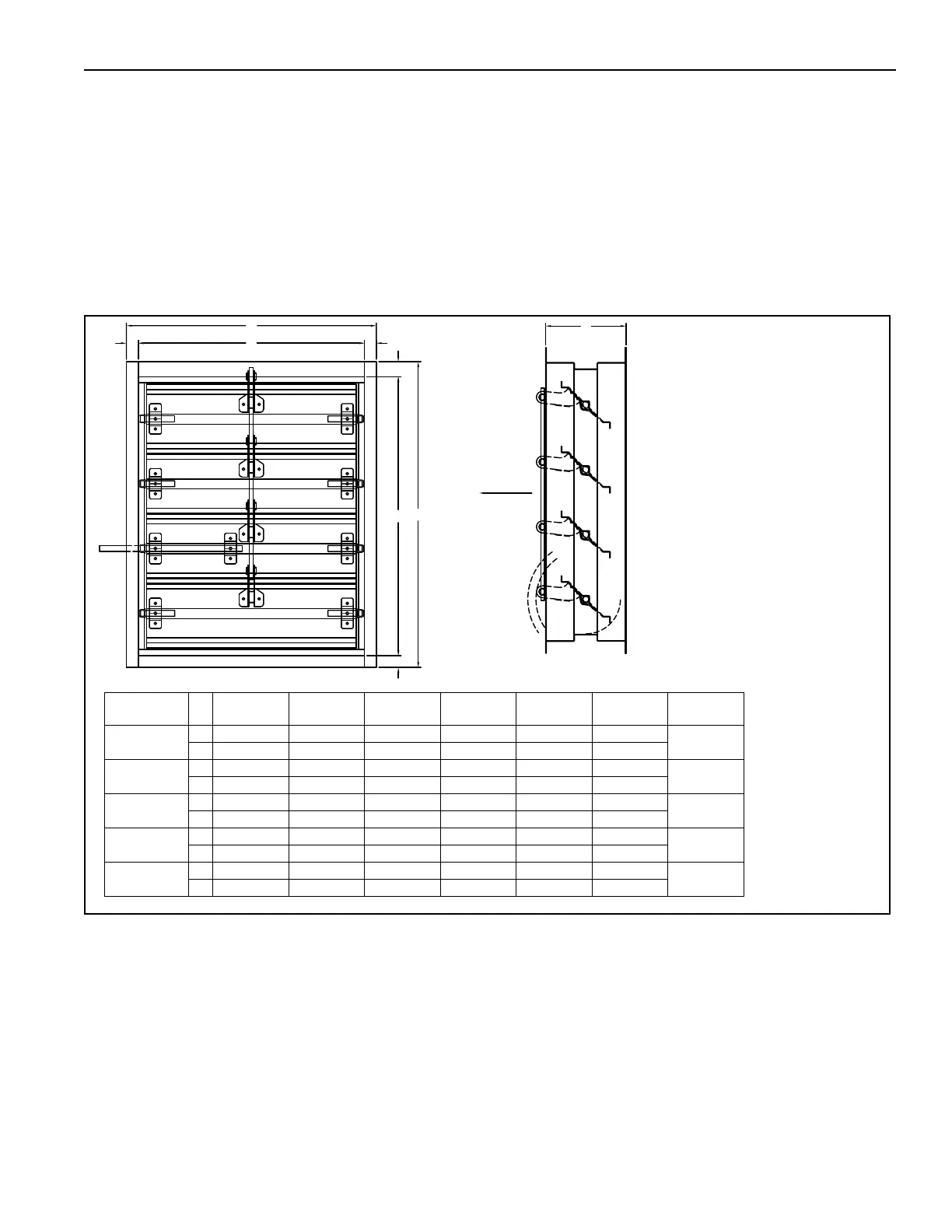
FIGURE 14: Motorized Discharge Damper (XT-112 - XT-130)
12.2 Inlet Damper
Inlet dampers are factory mounted to the inlet of the air handler (covering the inlet opening). The inlet
damper has four outward-turned flanges. Based on air handler style, damper may include upper and lower
damper.
C
E
C
D
A
B
C
C
F
NOTE:1) CONTRACTOR/INSTALLER MUST MAKE
APPROPRIATE ALLOWANCES FOR DUCT
CONNECTIONS.
2) NUMBER OF LOUVERS WILL VARY.
3) MOUNTED DOWNSTREAM OF AIR HANDLER IN
DUCT WORK. DOES NOT MOUNT DIRECTLY TO
AIR HANDLER. FIELD WIRED TO PROVIDED
TERMINALS ON CONTROL PANEL.
AIR FLOW
Model A B C D E F
Weight
lbs (kg)
XT-112
in 18.6 15.6 1.5 16.5 13.5 8.0
25 (11)
cm 47.2 39.6 3.8 41.9 34.2 20.3
XT-115
in 28.0 25.0 1.5 26.1 23.1 8.0
51 (23)
cm 71.1 63.5 3.8 66.2 58.6 20.3
XT-118
in 30.8 27.8 1.5 30.6 27.6 8.0
65 (29)
cm 78.2 70.6 3.8 77.7 70.1 20.3
XT-125
in 34.3 31.3 1.5 34.6 31.6 8.0
83 (38)
cm 87.1 79.5 3.8 87.8 80.2 20.3
XT-130
in 39.8 36.8 1.5 39.8 36.8 8.0
111 (50)
cm 101.0 93.4 3.8 101.0 93.4 20.3