SERIES XT INSTALLATION, OPERATION AND SERVICE MANUAL
32
SECTION 13: DISCHARGE HEADS AND SPLASH PLATES
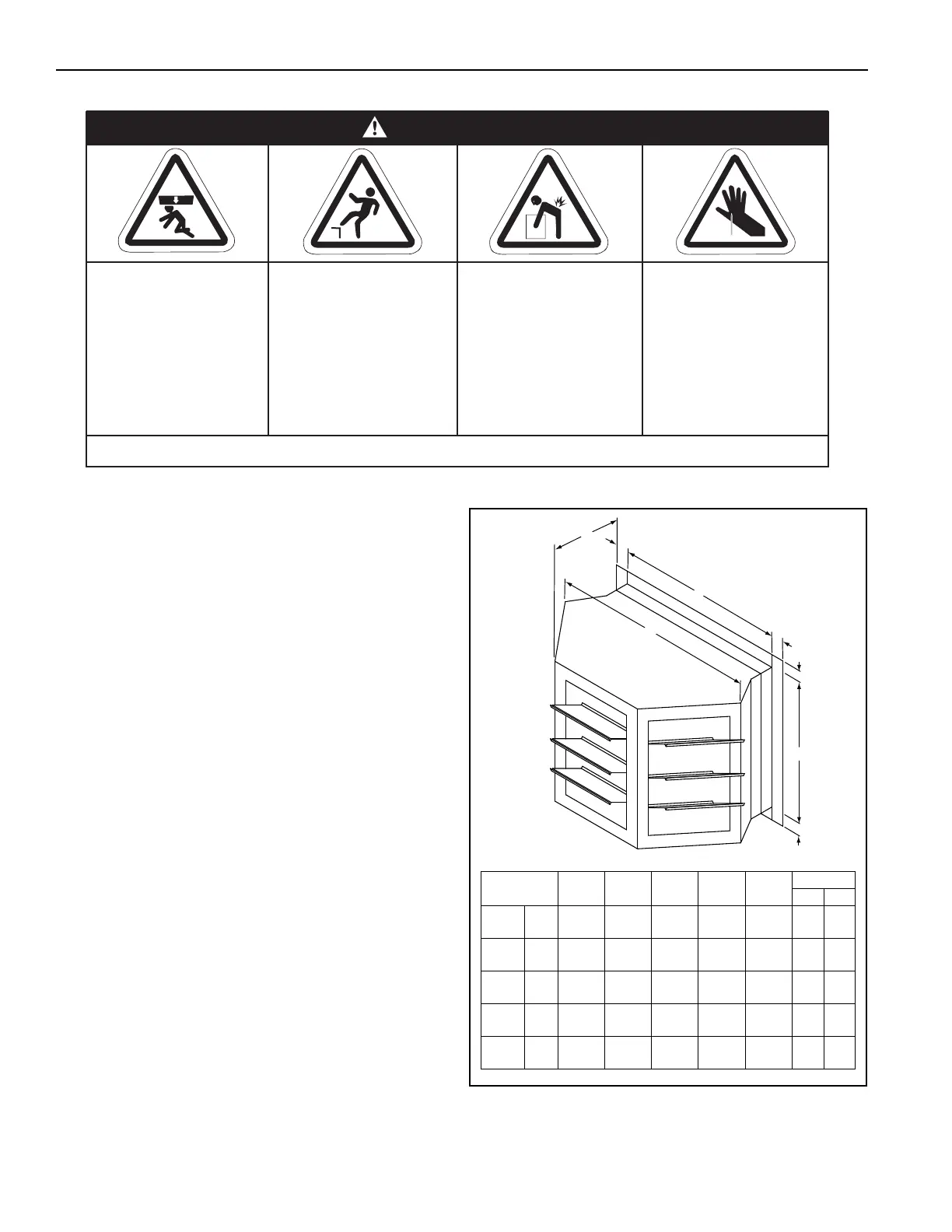
13.1 Three-Way Discharge Head Installation
All discharge heads are shipped assembled. The
discharge head is designed for mounting to the face
of the air handler (covering the discharge opening) or
to an interior wall. All discharge heads must be field
supported (by others). The discharge head has four
outward-turned flanges. If the discharge head is to
be installed to the face of the air handler, install
hardware (provided by others) on all four sides of the
discharge head.
To install the discharge head on an interior wall, drill
holes every 8" (20.5 cm) in the flanges on all four
sides of the discharge heads to accommodate lag
bolts (supplied by others). Sheet metal (supplied by
others) may be required. See Page 32, Figure 15 for
the three-way discharge head available.
FIGURE 15: Three-Way Discharge Head
Crush Hazard
Use proper lifting
equipment and
practices.
Falling Hazard
Use proper safety
equipment and prac-
tices to avoid falling.
Severe Injury Hazard
Use proper lifting
practices and equip-
ment.
Equipment and
accessories are
heavy.
Cut/Pinch Hazard
Wear protective gear
during installation,
operation and
service.
Edges are sharp.
WARNING
Failure to follow these instructions can result in death, injury or property damage.
Model ABCDE
Weight
lbs kg
XT-
112
(in)
(cm)
16
(40.6)
35.5
(90.2)
22.8
(57.9)
13.6
(34.5)
2.0
(5.1)
40 18
XT-
115
(in)
(cm)
23.4
(59.4)
55.7
(141.5)
35.2
(89.4)
25.3
(64.3)
2.0
(5.1)
50 23
XT-
118
(in)
(cm)
27.8
(70.6)
55.7
(141.5)
35.8
(90.9)
27.8
(70.6)
2.0
(5.1)
84 38
XT-
125
(in)
(cm)
34.5
(87.6)
77.3
(196.3)
47.7
(121.2)
32.4
(82.3)
2.0
(5.1)
120 54
XT-
130
(in)
(cm)
37.4
(95.0)
86.8
(220.5)
51.8
(131.6)
37.4
(95.0)
2.0
(5.1)
160 73