6.4 Electrical
Parts
6.4.1
Electronic Control Unit
Description:
Upon start-up, the control unit takes over
the complete control of the functional sequence of the
heater operation (see section 5 "Functional Descrip-
tion"). For this purpose, it evaluates the signals re-
ceived from the flame detector as well
as
the
full
load/part load functions of room thermostats or swit-
ches.
Check: Checking the control units (SG
1561
and
SG
1561
GT) can only
be
accomplished
by
means of the
Webasto testing device (see section
7.2.1
).
Repair: Any defective control unit must
be
replaced
as
a complete unit.
Note: The components such as control unit, pulse-con-
trolled glow plug relay and part load resistor for the
12
V system are identified by a red ·label, those compo-
nents for the
24
V systems by a green label.
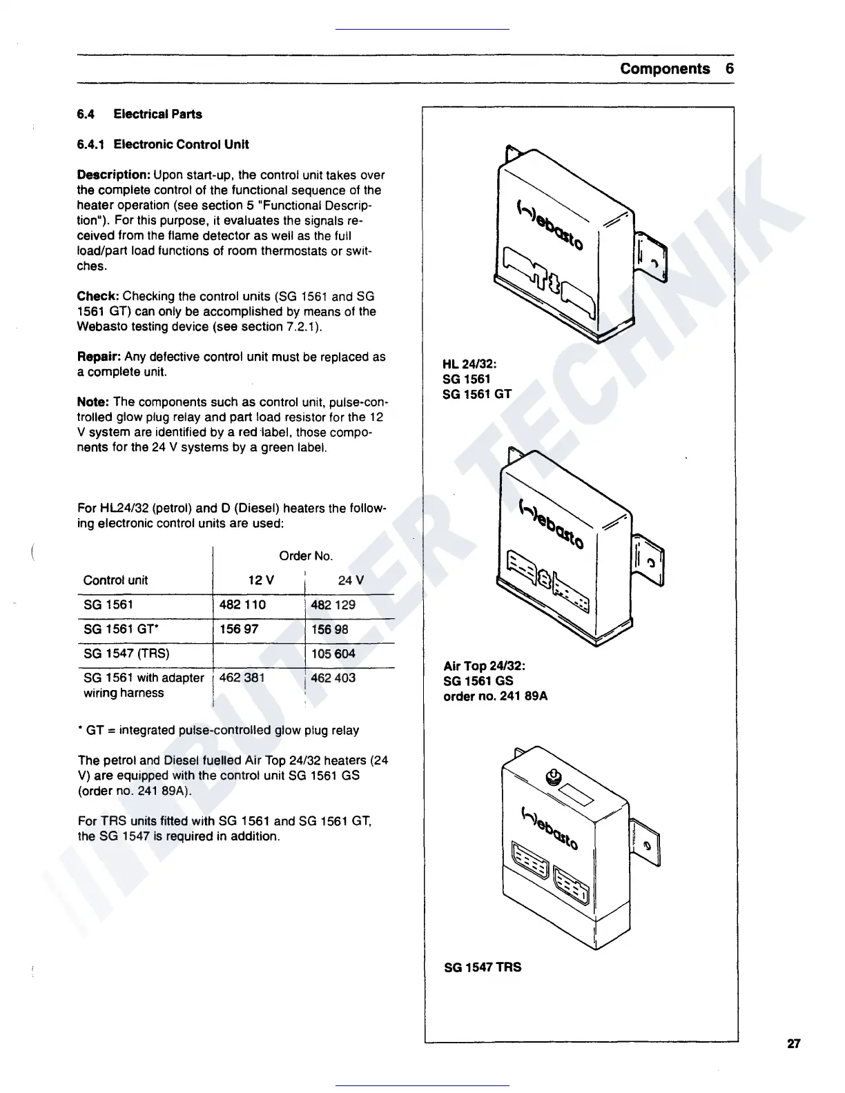
For HL24/32 (petrol) and D (Diesel) heaters the follow-
ing electronic control units are used:
Control unit
12V
SG
1561
482 110
SG
1561
GT*
15697
SG
1547 (TRS)
SG
1561
With
adapter 1462
381
wiring harness
Order
No.
I
24V
482129
156
98
105 604
j 462403
• GT = integrated pulse-controlled glow plug relay
The petrol
and
Diesel fuelled Air Top 24/32 heaters (24
V)
are equipped with the control unit
SG
1561
GS
(order no.
241
89A).
For TAS units fitted with SG 1561 and
SG
1561
GT,
the SG 1547
is
required in addition.
Components
6
HL 24/32:
SG
1561
SG
1561
GT
("'L
~b~()
/
...
...
.......
......
..
.
..
Air
Top
24/32:
SG
1561
GS
order no.
241
89A
SG
1547TRS
27
 Loading...