48
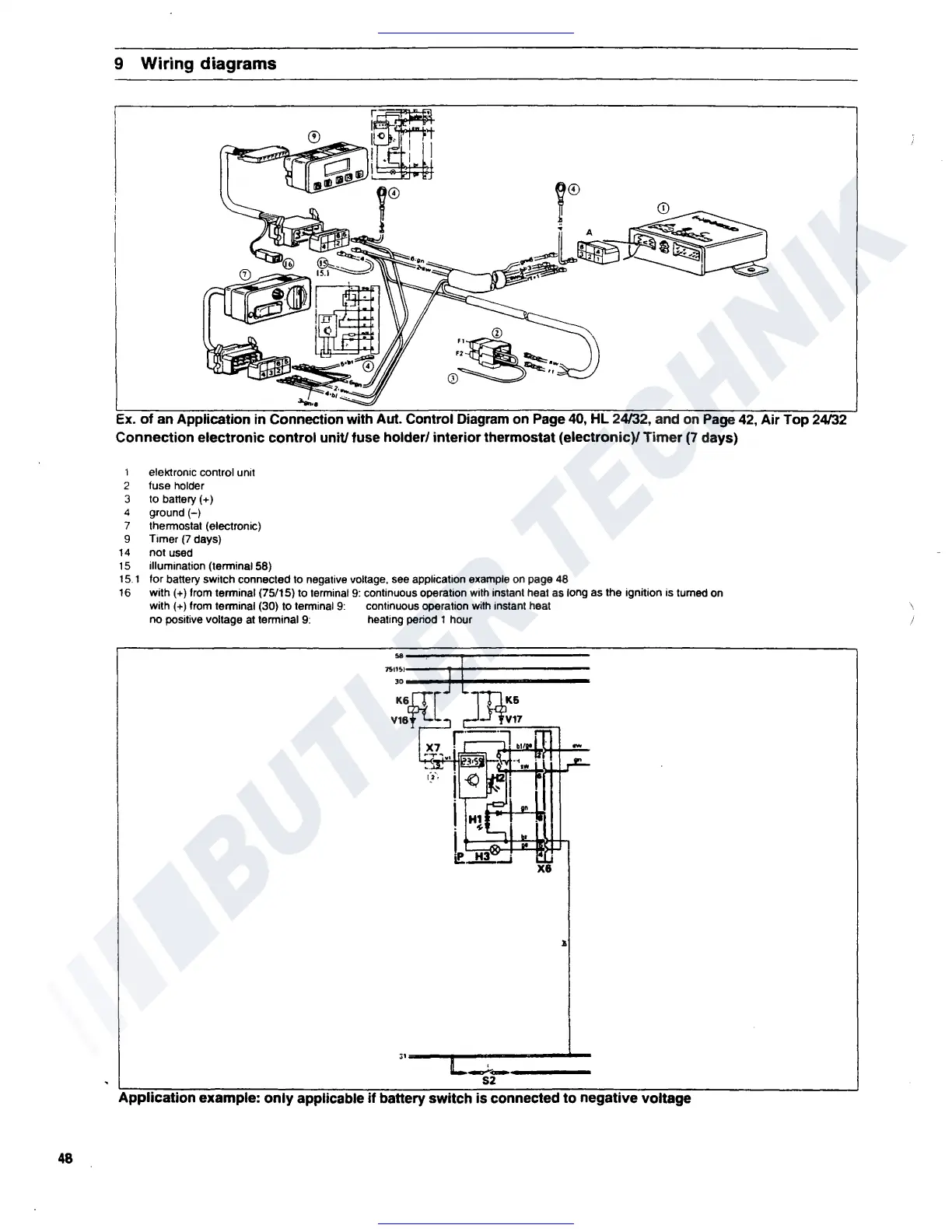
9 Wiring diagrams
CD
Ex.
of
an Application in Connection wit ut. Control Diagram on
Page
40,
HL 24/32, and
on
Page
42,
Air Top 24/32
Connection electronic
control
unit/ fuse holder/ interior thermostat (electronic)/
Timer
(7
days)
1 elektronrc control unit
2 fuse holder
3 to battery(+)
4
ground(-)
7 thennostat (electronic)
9 Timer
(7
days)
14
not used
15
illumination (terminal 58)
15.
1 for battery switch connected to negative voltage,
see
application example
on
page 48
16
with(+) from tenninal (75/15) to
1erminal
9:
continuous operation
with
instant heat as long as the ignition is turned on
with(+) from tenninal (30) to terminal
9:
continuous operation wilh instant heat
no positive voltage
at
terminal
9:
healing period 1 hour
..
JS•::·
]
v::H:[
~t~~i;~~i:.itt.+-,
xe
.I
·•---..---------
--------
S2
Application example: only
applicable
if
battery
switch
is
connected
to
negative voltage
\
/
 Loading...