Wiring diagrams 9
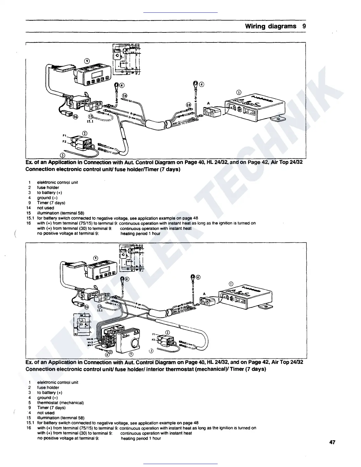
Ex.
of
an Application
in
Connection with Aut. Control Diagram
on
Page
40,
HL
24fJ2, and on Page
42,
Air Top 24fJ2
Connection electronic control
unit/
fuse holderfTimer
(7
days)
1 elektronic control unit
2 fuse holder
3 to battery (+)
4 ground
H
9 Timer (7 days)
14
not used
15
illumination (terminal 58)
15.1
for battery switch connected
to
negative voltage, see application example
on
page 48
16
with(+) from terminal (75/15)
to
terminal
9:
continuous operation
with
instant heat as
long
as
the
ignition
is
turned
on
with(+) from terminal (30)
to
terminal
9:
continuous operation with instant heat
no positive voltage at terminal
9:
heating
period
1
hour
m
I .
I<>
I
I . I I
Ex.
of
an Application
in
Connection with Aut. Control Diagram
on
Page
40,
HL 24/32, and on Page 42, Air Top 24/32
Connection electronic control
unit/
fuse holder/ interior
thermostat
(mechanical)/ Timer (7
days)
1 eleklronic control unit
2 fuse holder
3 to battery ( +)
4
ground(-)
5 thermostat (mechanical)
9 Timer (7 days)
·4 not used
15
illumination (terminal 58)
15.1
for battery switch connected
to
negative voltage, see application example on page 48
16
with (+) from terminal (75/15) to terminal
9:
continuous operation with instant heat as
long
as
the ignition is turned on
with(+) from terminal (30) to terminal
9:
continuous operation with instant heat
no positive voltage at terminal
9:
heating
period
1
hour
47
 Loading...