Intelligent Fast-Charging System
GSE O&M for DVS300 / 330 / 330 IP55 / 400 and MVS330/400
31504-03-0101 Webasto Charging Systems, Inc.17
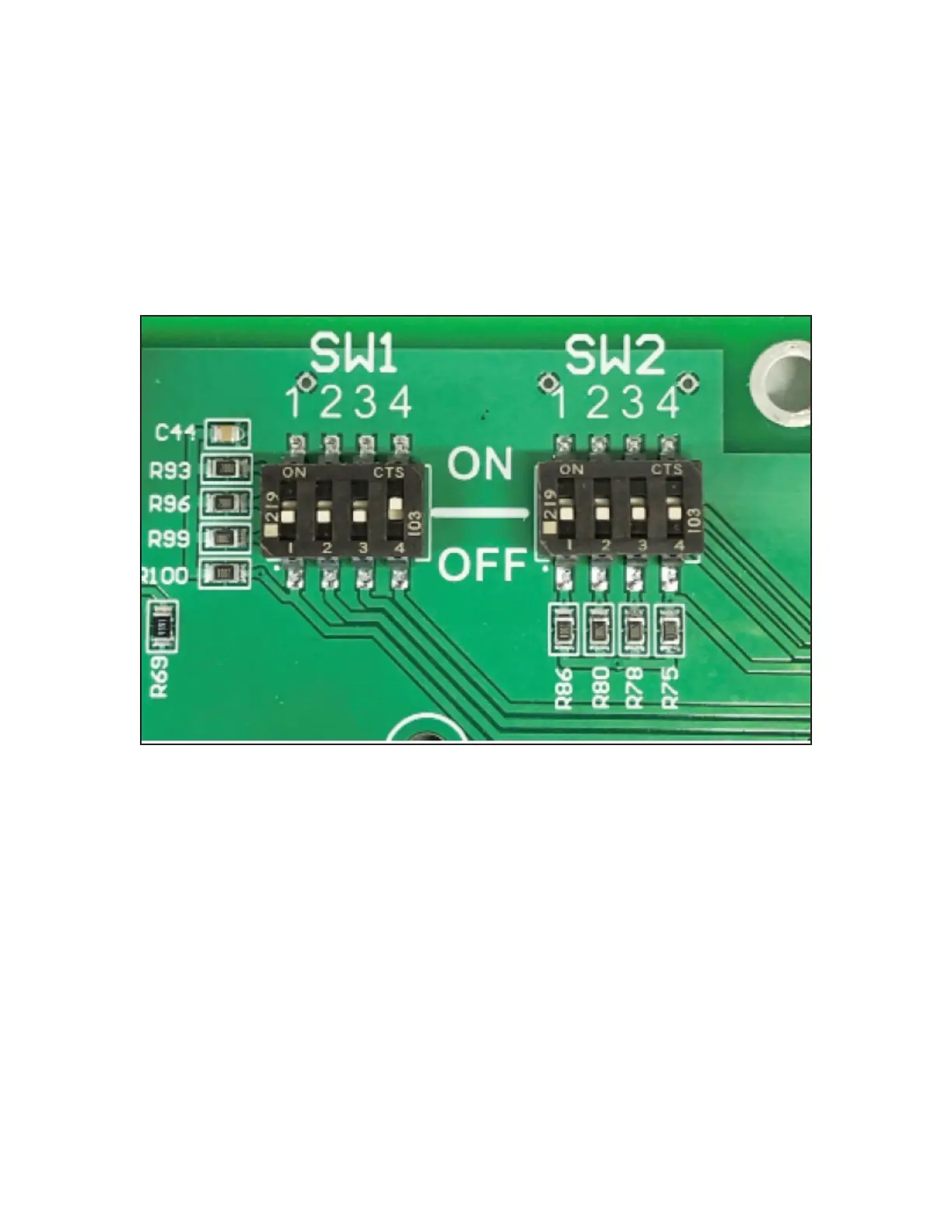
4. Set the control board SW1-4 DIP switch in the DIP switch bank (Figures 4 and 5) to the ON position to
enable the parallel-mode operation.
• Figure 5 shows a detailed view of the [SW1-4] DIP switch in the parallel conguration. When parallel
operation is enabled and only one vehicle is connected to the power station then both power sections
in the charger are combined to deliver maximum power.
• The installation software utility program then sets the maximum port current conguration. If the
SW1-4 switch is set to the OFF position, then this conguration is limited based on the model design.
5. Apply the power.
• The power station installed and wired nearest to the power server must be congured as the main station
of the system and all other power stations as support stations. This conguration is accomplished through
the use of the front-panel conguration menus (Figure 3).
• The factory default setting for all power stations is the support setting.
Figure 5 – Detailed View of the DIP Switch in Parallel Conguration