Do you have a question about the Weber genesis II E-210 GBS and is the answer not in the manual?
Assemble on a flat surface; requires two people, no power tools.
Remove protective film from stainless steel; note potential visual differences.
Secure retainer clips to the wheel axle for proper wheel attachment.
Attach the main wheels to the grill frame.
Connect the main frame components to build the grill's base structure.
Fasten the wheels onto the grill frame using the provided clips.
Attach the swivel casters to the designated points on the grill frame.
Place the drip tray onto the lower rack for proper alignment.
Fasten the drip tray to the rack using the designated clips.
Insert the cooking grates and any heat deflectors into the grill body.
Mount the side shelves to the main grill frame using screws.
Attach the side panels to the grill frame structure.
Fasten the side panels to the grill frame with screws and clips.
Ensure electrical wires are routed on the inside of the grill frame.
Ensure the gas line is routed on the outside of the grill frame.
Illustrates correct wire routing for proper function and safety.
Attach the igniter module and related parts to the grill.
Secure the front panels to the grill body using screws.
Mount the front shields to the grill structure with screws.
Connect the gas hose to the burner manifold assembly securely.
Attach the storage box or tray to the grill frame.
Refer to troubleshooting for match lighting instructions.
Install a specific part required only for the 410 model.
Install specific parts required for the 210 and 310 models.
Mount the grill lid onto the main body.
Demonstrates the correct procedure for closing the lid.
Make adjustments to components if necessary for proper fit.
Attach the side shields to the grill frame.
Fasten the side panels to the grill body.
Secure the igniter clip to its designated mounting point.
Connect the gas line to the control valve assembly.
Note: Do not tighten screws completely at this stage.
Route electrical wires and gas lines correctly within the unit.
Fasten the igniter control box to the grill frame.
Connect the ignition wires to the spark module.
Mount the side panels to the grill frame using screws.
Insert the AA battery into the igniter module.
Illustrates the correct operation of the control knobs.
Place the warming racks into their designated positions.
Insert the main cooking grates onto the support ledges.
Secure the side panel or shelf to the grill frame.
Place the drip tray into the designated slot on the grill.
Adjust the warming rack to the lower position.
Adjust the warming rack to the upper position.
Attach the main grill lid to the body.
Fasten the grill lid securely to the frame.
Ensure all packing material is removed from the grill.
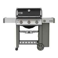
| Main Burners | 2 |
|---|---|
| Primary Cooking Area | 380 square inches |
| Side Tables | 2 |
| Tool Hooks | 6 |
| Gourmet BBQ System Cooking Grates | Yes |
| Main Burner BTU-per-hr Input | 26, 000 |
| Fuel Type | Liquid Propane |
| Grates | Porcelain-enameled cast iron |
| Burners | 2 |
| Warranty | 10 years |