Installation and Connection
CPW17 | 11
English
3 INSTALLATION AND CONNECTION
3.1 CONNECTIONS
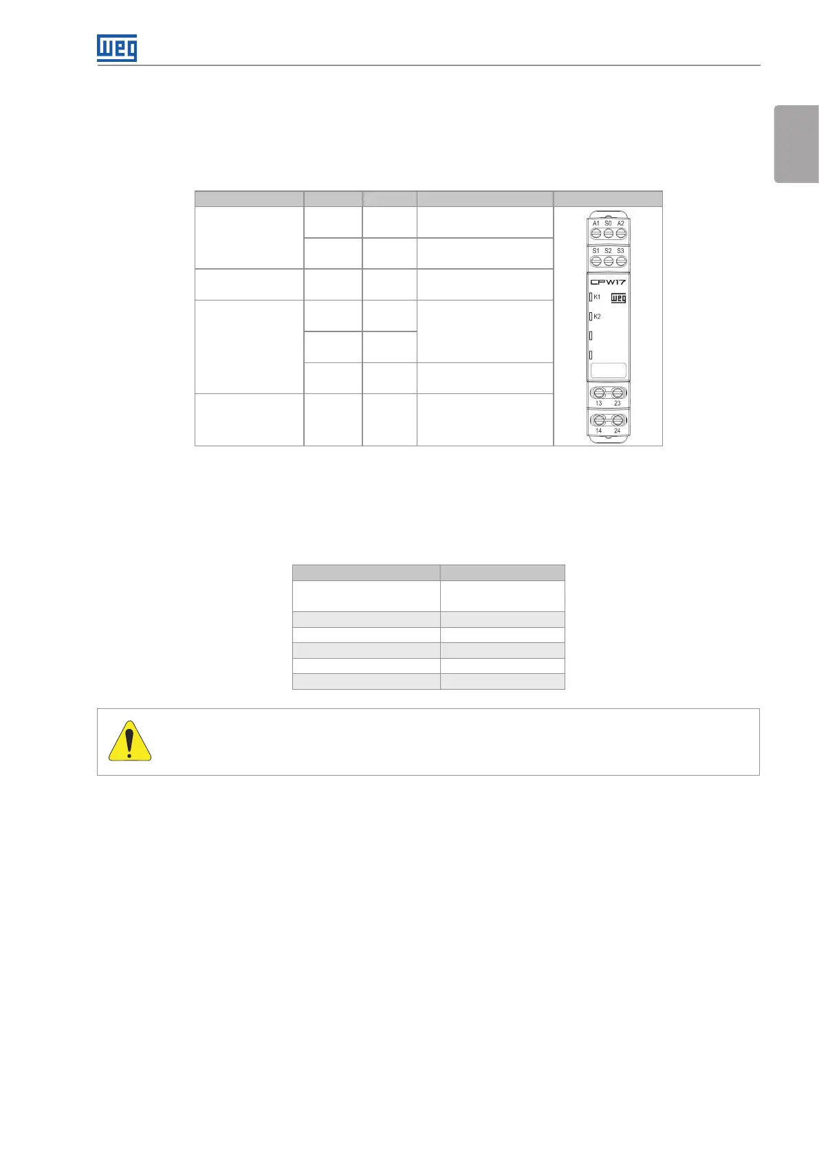
Table 3.1: Connection descriptions
Description Type Pin Function Front View
Power supply
IN A1 AC / DC Positive [+]
IN A2 AC / DC Negative [-]
Controlled voltage OUT S0 Positive reference [+]
Digital inputs
IN S1
Dual Channel PNP Input
IN S2
IN S3 PNP Start Control
Relay outputs OUT
13-14
23-24
Output Current paths 2
NO contacts
CONNECTION INSTRUCTIONS
The electrical connection of the safety relay for other devices is carried out by fixed terminals with screws. To
ensure the electrical connections integrity the following connection instructions must be considered:
Table 3.2: Electrical connection instructions
Parameter Value
Cable section
24 to 12 AWG
0.5 to 2.5 mm²
Cable resistance ≤ 40 Ω
Cable length of control line ≤ 100 m
Connection type Screw terminals
Tool Screwdriver slot Nº3
Torque ≤ 0.4 N.m.
ATTENTION!
Ensure that safety relay is turned off before perform the electrical connections. Do not use the safety
relay like supply to external devices.