www.weg.net
11371757 Installation, operation and maintenance manual – Squirrel cage motor – M line – Vertical l 21
4 INSTALLATION
4.1 INSTALLATION SITE
Electric motors must be installed in easily accessible
places, allowing periodic inspections, on-site maintenance
and, if necessary, removal for external services.
The following environmental conditions must be ensured:
Clean and well-ventilated location;
The installation of other equipment or walls must not
block or hinder the motor ventilation;
The area around and above the motor must be
sufficient for maintenance or handling;
The environment must be in accordance with the motor
protection degree.
4.2 SHAFT LOCK
4.2.1
Axial lock
The motor leaves the factory with a lock on the shaft to
prevent damages to the bearings during transportation.
This lock must be removed prior to motor installation.
shaft-locking device must be installed
whenever the motor is removed from its base
(uncoupled) in order to prevent damages to
the bearings during transportation.
The shaft end is protected at the factory with
a temporary protective agent (rust inhibitor).
During the motor installation, it is necessary
to remove this product from the grounding
brush (if any) contact track on the shaft.
4.2.2
Radial lock
Depending on the bearing type, a locking device may be
installed in the upper bearing for radial shaft locking during
transportation. This device is identified on the motor with
an adhesive label, as shown in Figure 4.1.
Figure 4.1: Adhesive label
It is imperative that before starting the motor this device is
removed and replaced with the original bearing seal which
is supplied loose.
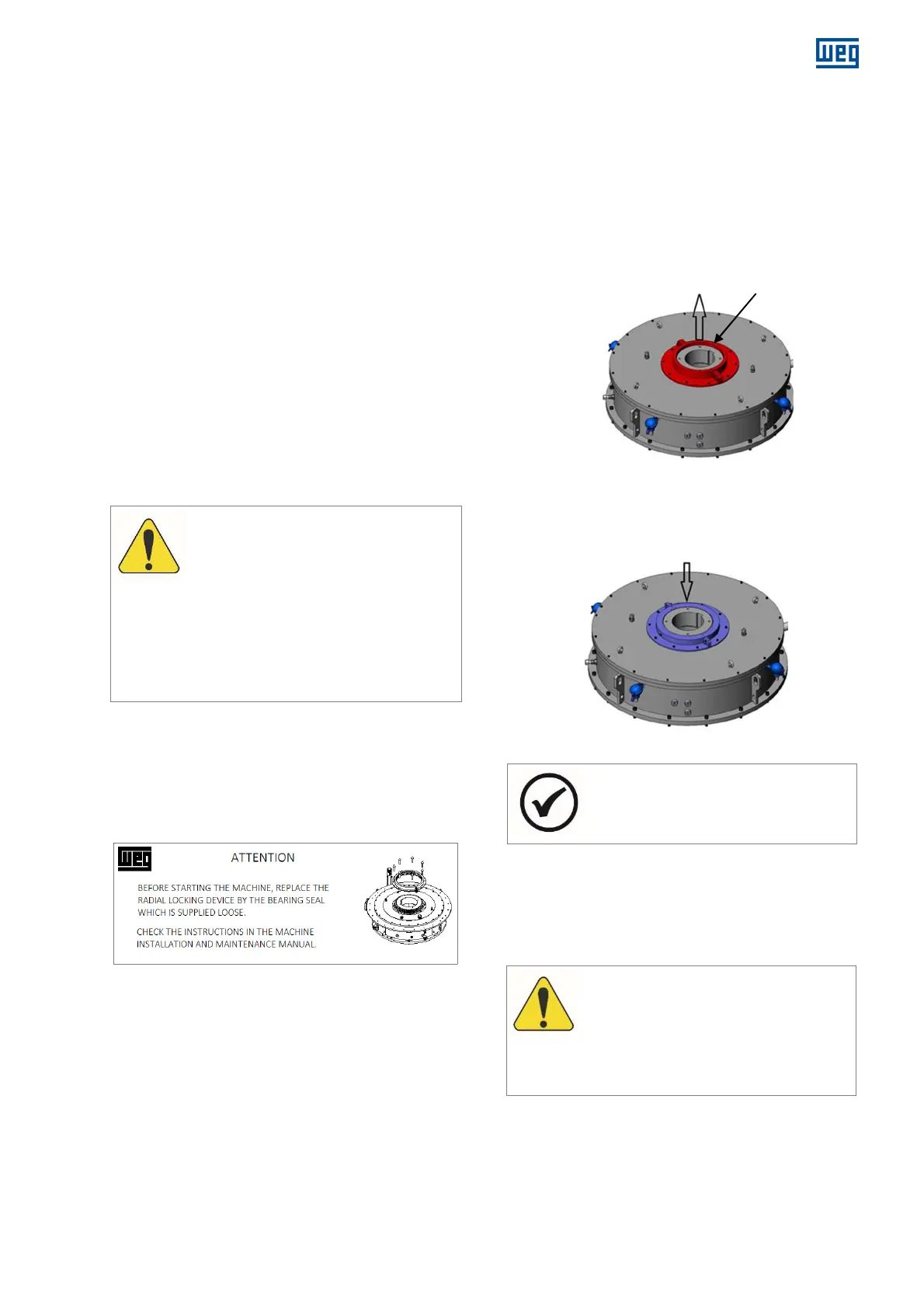
4.2.3
Procedure for replacing the radial locking
device
1. Remove the fastening screws from the locking device
on bearing cap;
2. Remove the screws that attach the two parts of the
split device;
3. Remove the locking device as show in Figure 4.2 ;
Radial locking device
Figure 4.2: Radial locking device
4. Identify the external bearing seal, supplied loose;
5. Fit the seal on bearing, following the disassembling
reverse procedure of the locking device.
Figure 4.3: Bearing seal
NOTE
Store the radial locking device for use in
future transport of the motor.
4.3 ROTATION DIRECTION
The motor rotation direction is indicated by a plate affixed
to the frame on the drive end and in the motor specific
documentation.
Motors supplied with a single rotation
direction must not operate in the opposite
direction.
In order to operate the motor in the direction
opposite to the specified, consult WEG.

 Loading...


