6 | Electric motors for explosive atmospheres
For motors with degree of protection IP56, IP65 or IP66, the drain plugs must remain at closed position, being opened only during the motor maintenance procedures.
"Automatic" rubber drain plugs are designed for one use only and cannot be reused. If any drain plug is removed for any purpose, it must always be replaced by a new one.
The drain system of motors with Oil Mist lubrication system must be connected to a specific collection system.
The drain plugs of explosion proof motors cannot be removed during installation and maintenance procedures.
When provided with a breather-drain to certificates IECEx CSA 12.0005U, Sira 12ATEX1245U, CSAE 21UKEX1299U, the motors are limited to Groups II and III, an ambient temperature
of -55 °C to +50 °C for temperature class T5 and -55 °C to +80°C for temperature class T4 to T2.
Do not cover or block the motor ventilation openings. Ensure a minimum clearance of ¼ of the diameter of the air intake of the fan cover from the walls.
The air used for cooling the motor must be at ambient temperature, limited to the temperature range indicated on the motor nameplate (when not indicated, -20 °C to +40 °C must
be considered).
Motors installed outdoors or in the vertical position require the use of additional shelter to protect them from water; for instance, use of a drip cover.
To prevent accidents, ensure that the grounding connection has been performed according to the applicable standards and that the shaft key has been securely fastened before
the motor is started.
Connect the motor properly to the power supply by means of safe and permanent contacts, always considering the data informed on the nameplate, such as rated voltage, wiring
diagram, etc.
When motors are supplied with flying leads, they must be suitably connected to an appropriate terminal box required for the use condition (type of protection).
When using terminals, all wires that form the stranded cable must be fastened inside the sleeve. The insulation of the accessories cables must be kept up to 1 mm from the connector
connection point.
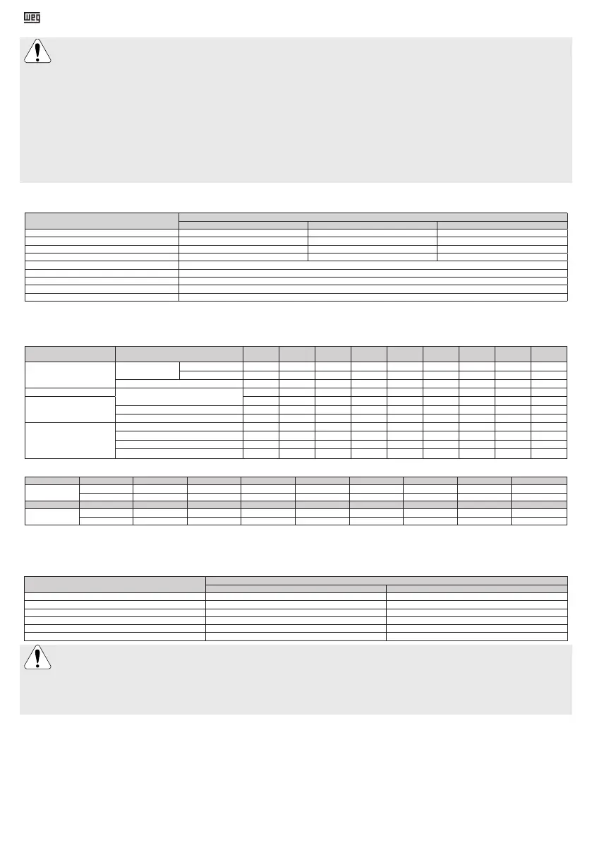
When provided with terminal blocks marked with “W-A12”, “W-B12 (160V)” or “W-B12 (500V)”, the following characteristics must be respected:
Table 1 - Terminal block type designation
Characteristic
Terminal block type designation
W-A12 W-B12 (160 V) W-B12 (500 V)
Voltage Up to 160 V Up to 160 V Up to 500 V
Current Max. 15 A Max. 15 A Max. 20 A
Conductor cross-section 0,3 to 2,5 mm² 0,3 to 4 mm² 0,3 to 4 mm²
Number of cables per terminal connection 2x1 mm² 2x1,5 mm² 2x1,5 mm²
Connection torque 0,5 to 0,7 Nm
Service temperature -20 °C to + 80 °C
ATEX marking/certificate II 2G Ex eb IIC Gb / I M2 Ex eb I Mb / PTB 06 ATEX 1078 U
IECEx marking/certificate Ex eb IIC Gb / Ex eb I Mb / IECEx PTB 17.0014U
UKEX marking/certificate II 2G Ex eb IIC Gb / I M2 Ex eb I Mb / BAS21UKEX0454U
When provided with an "Ex eb" terminal block according to certificates PTB 03 ATEX 1153 U/IECEx PTB 11.0088U / BAS21UKEX0453U, it is permitted a maximum
of 2 (two) single-wire cables per terminal connection. For power cables and grounding system connections and terminal box assembly, the tightening torques
indicated on Tables 2 and 3 must be respected.
Table 2 - Tightening torques for fixing elements [Nm]
Type of protection
of enclosure
Component M4 M5 M6 M8 M10 M12 M14 M16 M20
Ex db
Ex db eb
Terminal Box Cover
Class 8.8/12.9 - 3,5 to 5 6 to 12 14 to 30 28 to 60 45 to 105 75 to 110 115 to 170 230 to 330
Class A2-70 / A4-70 - 3,5 to 5 6 to 8,5 14 to 19 28 to 40 45 to 60 75 to 100 115 to 170 225 to 290
Grounding 1,5 to 3 3 to 5 5 to 10 10 to 18 28 to 40 45 to 70 - 115 to 170 -
Ex db
Terminal block
1 to 1,5 2 to 4 4 to 6,5 6,5 to 9 10 to 18 15,5 to 30 - 30 to 50 50 to 75
Ex db eb
1 to 1,5 2 to 4 4 to 6,5 6,5 to 9 5 to 9 10 to 15 - 20 to 30 -
Locking bolt for connection clamp - 3 to 7 4 to 8 7 to 11 - - - - -
Locking bolt for power cables - - - 2 to 6 6 to 10 - - - -
Ex ec
Ex tb
Ex tc
Ex eb
Terminal box cover - 3 to 5 4 to 8 8 to 15 18 to 30 25 to 40 30 to 45 35 to 50 -
Grounding 1,5 to 3 3 to 5 5 to 10 10 to 18 28 to 40 45 to 70 - 115 to 170 -
Terminal block 1 to 1,5 2 to 4 4 to 6,5 6,5 to 9 10 to 18 15,5 to 30 - 30 to 50 50 to 75
Terminal block fixing bolts - 3 to 5 5 to 10 10 to 18 28 to 40 45 to 70 75 to 110 115 to 170 -
Table 3 - Tightening torques for cable glands and plugs [Nm]
Thread Material M16 M20 M25 M32 M40 M50 M63 M80
Metric
Plastic 3 to 5 3 to 5 6 to 8 6 to 8 6 to 8 6 to 8 6 to 8 6 to 8
Metallic 40 to 50 40 to 50 55 to 70 65 to 80 80 to 100 100 to 120 115 to 140 160 to 190
Thread Material NPT 1/2" NPT 3/4" NPT 1" NPT 1 1/2" NPT 2" NPT 2 1/2" NPT 3" NPT 4"
NPT
Plastic - 5 to 6 6 to 8 6 to 8 6 to 8 6 to 8 6 to 8 6 to 8
Metallic 40 to 50 40 to 50 55 to 70 65 to 80 100 to 120 115 to 140 150 to 175 200 to 240
For power cables, switching and protection devices dimensioning, consider the rated motor current, the service factor, and the cable length, among others.
For motors without terminal block, insulate the motor terminal cables by using insulating materials that are compatible with the insulation class informed on the
nameplate. The minimum insulation distance between the non-insulated live parts themselves and between live parts and the grounding must respect the Table 4.
Table 4 - Minimum insulation distance (mm)
Voltage
Type of protection of the enclosure
Ex eb / Ex db eb Ex ec / Ex db / Ex tb / Ex tc
U ≤ 440 V 6 4
440 < U ≤ 690 V 10 5,5
690 < U ≤ 1000 V 14 8
1000 < U ≤ 6900 V 60 45
6900 < U ≤ 11000 V 100 70
11000 <U ≤ 16500 V - 105
Take the required measures in order to ensure the type of protection, the EPL and the degree of protection indicated on the motor nameplate:
- unused cable inlet holes in the terminal boxes must be properly closed with certified plugs;
- components supplied loose (for example, terminal boxes mounted separately) must be properly closed and sealed;
The cable entries used must be fitted with components (such as, cable glands and conduits) that meet the applicable standards and regulations for each country.
For “Ex db” motors, the conduit entries are permitted only for electrical equipment of group II.
The fixing elements mounted in the threaded through holes in the motor enclosure (for example, the flange) must be properly sealed, with the products listed in item
5, to ensure the degree of protection indicated on the motor nameplate.
The motor must be installed with overload protection devices. These protection devices can be integrated to the motor (such as thermistors in the windings) or external protection
devices, where the motor load is monitored by the nominal current. For three-phase motors, it is recommended to install a phase failure protection device. Motors driven by variable
frequency drives must have their winding thermal protections connected. For motors with a soft start supply, effective measures for limiting the temperature of the motor shall be
provided by the installer according to the applicable installation standards. For other starting methods, the use of the thermal protections is optional. For “Ex ec”, “Ex db”, “Ex db
eb”, “Ex tb” and “Ex tc” motors: all thermal protections (RTDs, bimetal thermal protectors and thermistors for stator protection) used in the motor protection circuit can be connected
via a standard industrial controller located in a safe area.
For "Ex eb” motors: all thermal protections (RTDs, bimetal thermal protectors and thermistors for stator protection) must be suitably certified Ex equipment or they are to be
separately protected by the use of an intrinsic safety supply that ensures the minimum EPL Gb level of protection.
Ensure the correct operation of the accessories (brake, encoder, thermal protection, forced ventilation, etc.) installed on the motor before it is started.The temperature limits for alarm
and tripping of the thermal protection can be defined according to the application, however they may not exceed the values shown in Table 5.

 Loading...


