Electric motors for explosive atmospheres | 7
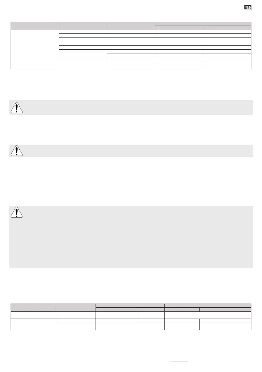
Table 5 - Maximum temperature of actuation for thermal protections
Component
Classified area marked on
nameplate
Classified area where product
will be installed
Maximum operating temperature (°C)
Alarm Tripping
Winding
Ex db Ex db 130 150
Ex ec Ex ec 130 155
Ex tb
Ex tc
Ex tb
Ex tc
120 140
Ex eb Ex eb - 110
Ex ec + Ex tc
Ex ec 140 155
Ex tc - 140
Ex db + Ex tb
Ex db 140 150
Ex tb - 140
Bearings All All 110 120
Notes:
1) The quantity and type of thermal protections installed in the motor are infomed in the additional nameplates included on it.
2) In case of calibrated thermal protection (for example, Pt-100), the monitoring system must be set at the operation temperature indicated on Table 5.
In “Ex eb” motors application, the thermal protection device, in case of overload or locked rotor, must actuate with time delay according to the current and track the
external power cables. The “t
E
” time indicated in the motor nameplate can not be exceeded. The “Ex eb” motors, submitted to acceleration time conditions greater
than 1,7 x “t
E
” time, must be protected with protection devices against overcurrent.
Motors fitted with Automatic Thermal Protectors will reset automatically as soon as the motor cools down. Thus, do not use motors with Automatic Thermal
Protection in applications where the auto-reseting of this device may cause injuries to people or damage to equipment.
If the Automatic Thermal Protector trips, disconnect the motor from the power supply and check the cause why the thermal protector trips.
For W60 motors with air-water heat exchanger, please see the nameplate at heat-exchanger.
For information about the use of variable frequency drives, you must follow the instructions in the documents 50034162 (“Installation, Operation and Maintenance Manual of Electric
Motors for Use in Explosive Atmospheres”) and 50029350 (“Induction motors fed by PWM frequency inverters” in the website www.weg.net and in the manual of the variable
frequency drive.
4. OPERATION
During operation, do not touch the non-insulated energized parts and never touch or stay too close to rotating parts.
Ensure that the space heater is always OFF during the motor operation.
The rated performance values and the operating conditions are specified on the motor nameplate. The voltage and frequency variations of the power supply should never exceed
the limits established in the applicable standards.
Occasional different behavior during the normal operation (actuation of thermal protections, noise level, vibration level, temperature and current increase) must always be assessed
by qualified personnel.
Do not use roller bearings for direct coupling. Motors fitted with roller bearings require a minimum radial load to ensure a proper operation.
For motors fitted with oil lubrication or oil mist systems, the cooling system must be ON even after the machine is OFF and until the machine is at complete standstill.
In case of failure in the lubrication and/or cooling system, turn the motor OFF immediatly. After complete standstill, the cooling and lubrication systems (if any exist) must be switched
OFF and the space heaters (when supplied) must be switched ON. In case of doubts, turn the motor OFF immediately and contact the nearest WEG Authorized Service Center
for Explosive Atmospheres.
5. MAINTENANCE
Before any service is performed, ensure that motor is at standstill, disconnected from the power supply and protected against accidental energization.
Even when the motor is stopped, dangerous voltages may be present in space heater terminals.
Motor disassembly during the warranty period must be performed by a WEG Authorized Service Center for Explosive Atmospheres only.
For motors with permanent magnet rotor (WQuattro and Magnet motors), the motor assembly and disassembly require the use of proper devices due to the
attracting or repelling forces that occur between metallic parts. This maintenance must be only performed by a WEG Authorized Service Center specifically trained
for such an operation. People with pacemakers cannot handle these motors. The permanent magnets can also cause disturbances or damages to other electric
equipment and components during maintenance.
Motors with flameproof enclosures and Protection by enclosure (Ex t), wait at least 60 minutes for frame sizes IEC 71 up to 200 and NEMA 143/5 up to 324/6 and at
least 150 minutes for frames sizes IEC 225 up to 355 and NEMA 364/5 to 586/7 to open the terminal box and/or disassemble the motor.
For easy removal of the terminal box cover for W22Xdb motors with terminal box integrated into the frame: remove a plug (if available) and then turn the terminal box
cover before performing the removal procedure. Reinstall the plug according to item 3 (Installation) after completing the maintenance procedures.
For the W51 HD, W50 and HGF motor lines provided with axial fans, the motor and the axial fan have different markings for indicating the direction of rotation for
prevent incorrect assembly. The axial fan must be assembled so that the indicative arrow for direction of rotation is always visible, viewing the non-drive end side.
The marking indicated on the axial fan blade, CW for clockwise direction of rotation or CCW for counterclockwise direction of rotation, indicates the direction of
rotation of the motor viewing the drive end side.
Motors with degree of protection greater than IP55 are supplied with a sealing product on joints and fixing bolts. Before assembly the components with machined faces (for
example, terminal box cover of Flameproof motors), clean these surfaces and apply a new layer of this product.
For Flameproof motors joints only the following products can be used: Lumomoly PT/4 (manufacturer: Lumobras – for ambient temperature ranging from -20 °C to +80°C) or
Molykote DC 33 (manufacturer: Dow Corning – for ambient temperature ranging from -55 °C to +80 °C). For motors with other types of protection, use Loctite 5923 (manufacturer:
Henkel) on joints. For Flameproof motors, special care should be taken with the machined surfaces of the flame path. These surfaces must be free of burrs, scratches,
etc. that reduce the flame path length and increase the gap. For any repair, contact WEG. The gaps between terminal boxes and the respective terminal box covers should not
exceed the values specified in Table 6.
Table 6 - Maximum gap between terminal box and terminal box cover for flameproof enclosures
Product line Frame size
Flat joint Cylindrical joint
Gap (max) Lenght (min) Gap (max) Lenght (min)
W21Xdb
IEC 90 to 355
NEMA 143 to 586/7
0,05 mm Under request Not available
W22Xdb
IEC 71 and 80 Not available 0,15 mm 12,5 mm
IEC 90 to 355
NEMA 143 to 586/7
0,075 mm 6 mm 0,15 mm 19 mm
For terminal box cover mounting, please follow the tightening torques indicated on Table 2 for fixing bolts.
In case of replacement of a fixing bolt, it is necessary to keep its dimensions and quality of material. For flameproof motors, the yield stress of the fastener elements of motor and terminal boxes
enclosures must be at least equal to class 12.9 for carbon steel bolts and class A2-70 or A4-70 for stainless steel bolts.
Motors which may have a potential risk of electrostatic charge accumulation, supplied duly identified, must receive proper cleaning and maintenance interventions, i.e. with the use of a damp cloth,
avoiding electrostatic discharges.
For Protection by Enclosure motors (groups I and/or III), the maximum permissible dust layer on the motor enclosure is five millimeters (5 mm).
Regularly inspect the operation of the motor, according to its application, and ensure a free air flow. Inspect the seals, the fastening bolts, the bearings, the vibration and noise levels, the drain
operation, etc. The lubrication interval is specified on the motor nameplate (more information in the manual 50034162 in the website www.weg.net).
 Loading...


