13
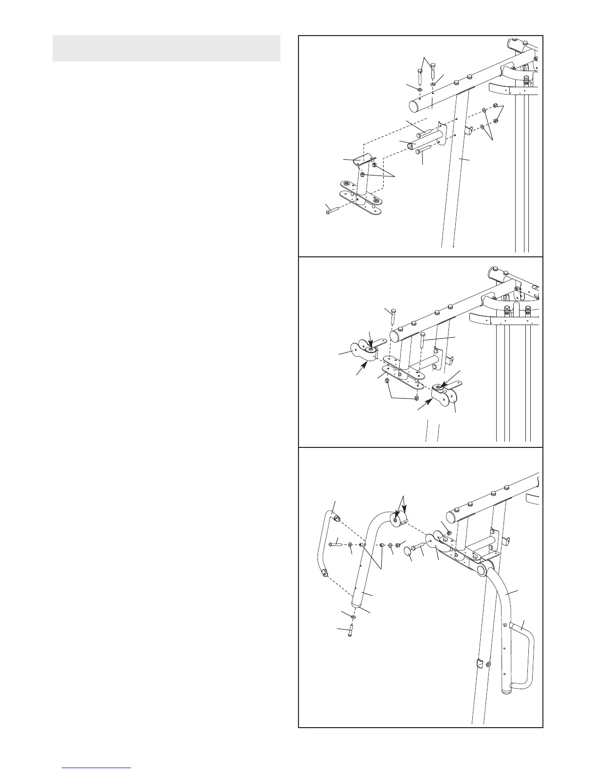
15. Attach the Butterfly Frame Brace (6) to the
R
ight Upright (2) with two M8 x 80mm Bolts
(100), two M8 Washers (103), and two M8
N
ylon Locknuts (78).
D
o not tighten the Nylon
Locknuts yet.
Attach the Butterfly Frame (5) to the Right Top
Frame (4) and the Butterfly Frame Brace (6)
with two M8 x 80mm Bolts (100), an M10 x
75mm Button Screw (118), two M8 Washers
(103), and two M8 Nylon Locknuts (78).
Tighten the M8 Nylon Locknuts (78) used in
this step.
16. Apply grease to the locations shown and attach
the Left Butterfly Bracket (28) to the Butterfly
Frame (5) with an M10 x 82mm Bolt (84) and
an M10 Nylon Locknut (77).
Repeat this step for the Right Butterfly
Bracket (29).
17. Remove the indicated Butterfly Arm Cap (43)
from the Right Butterfly Arm (26). Attach a
Butterfly Handle (27) to the Butterfly Arm with
an M10 x 65mm Button Bolt (106), two M10
Washers (80), two 13mm Steel Spacers (109),
and an M10 Nylon Locknut (77).
Attach the Butterfly
Arm Cap (43) to the Right
Butterfly Arm (26) with an M10 x 82mm Button
Screw (92) and an M10 Large Washer (105).
Repeat this step for the Left Butterfly Arm
(25) and the other Butterfly Handle (27).
Apply grease in the locations shown and attach
the Right Butterfly Arm (26) to the Right
Butterfly Bracket (29) with an M10 x 75mm Bolt
(82) and an M10 Nylon Locknut (77). Press a
Bolt Cap (44) onto the end of the Bolt. Do not
overtighten the Bolt; the Butterfly Arm must
be able to pivot freely
.
Repeat this step for the Left Butterfly Arm
(25).
16
29
77
28
84
84
5
17
27
26
25
27
82
80
80
109
105
92
106
29
44
77
77
118
4
2
6
100
1
00
103
100
103
103
5
78
78
15
Grease
Grease
Grease
Grease
43
Arm Assembly
Grease