18
15
23
12
20
15
66
68
50
48
6
7
16
17
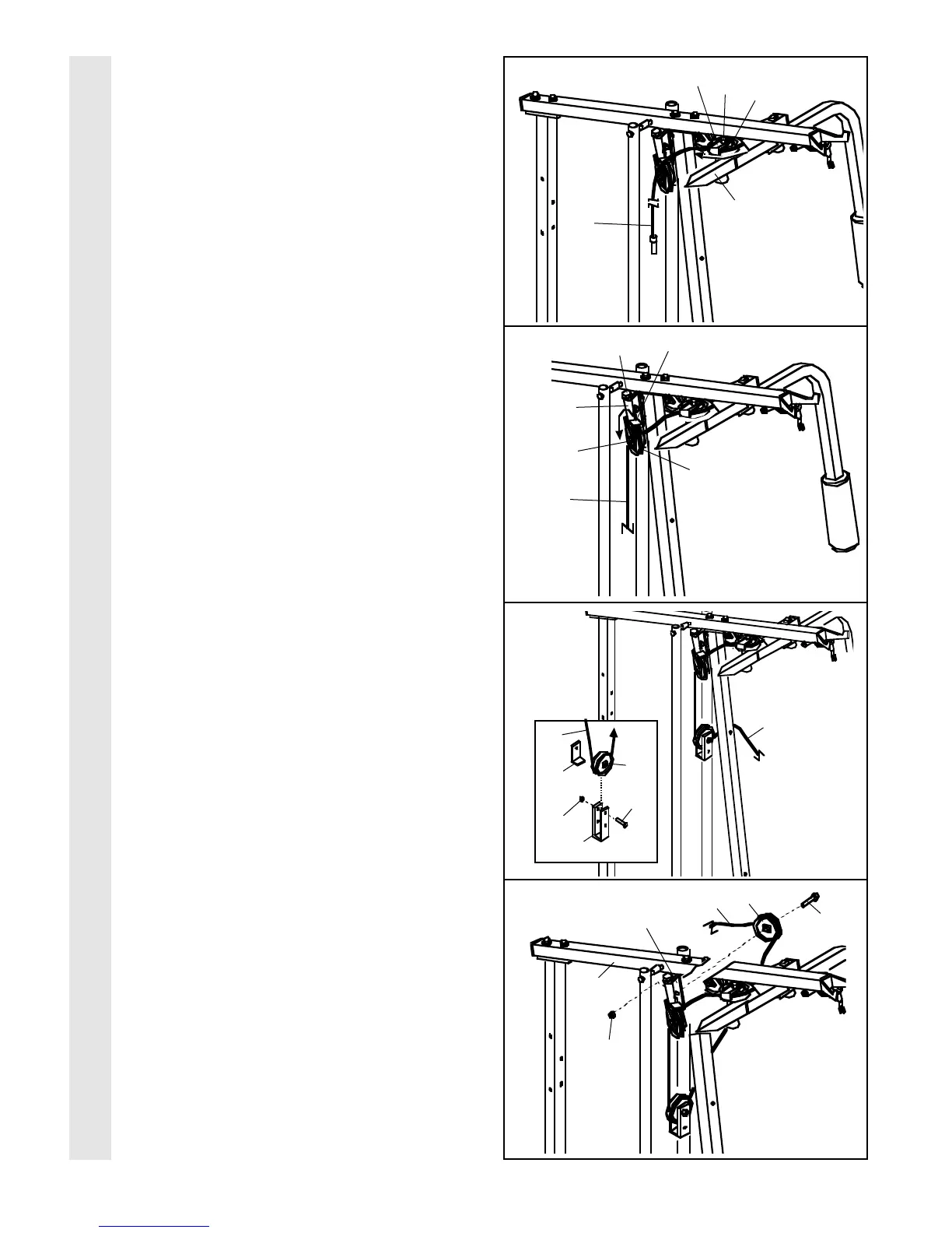
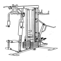
CABLE ASSEMBLY
10
15. Route the Long Cable (23) around the “V”-
Pulley (6) on the Right Arm (48). Be sure
that the Cable is in the groove of the “V”-
Pulley and that the Long Cable Trap (50) is
turned to hold the Cable in place. Tighten
the 3/8” x 2 1/2” Bolt (7) and the 3/8” Nylon
Locknut (not shown).
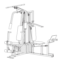
16. Route the Long Cable (23) around the 3 1/2”
Pulley (15) attached to the Pulley Bracket
(20). Be sure that the Cable is in the
groove of the Pulley and that the Cable
Trap (66) is turned to hold the Cable in
place. Tighten the 3/8” x 2” Bolt (12) and the
3/8” Nylon Locknut (not shown).
Make sure that the 5/16” x 5” Bolt (68) is
properly tightened and that the Pulley Bracket
(20) can move freely.
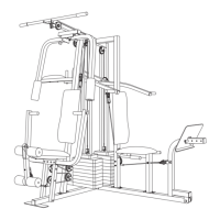
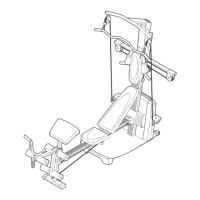
17. See the inset drawing. Attach a 3 1/2” Pulley
(15) and a Cable Trap (66) to the indicated
hole in the Long “U”-Bracket (57) with a 3/8” x
2” Bolt (12) and a 3/8” Nylon Locknut (21). Be
sure that the Cable Trap is inside the “U”-
Bracket. Note: This may come pre-assem-
bled.
Route the Long Cable (23) around the 3 1/2”
Pulley (15) and through the Long “U”-Bracket
(57). Be sure that the Cable is in the
groove of the Pulley and that the Cable
and Pulley move smoothly.
18. Note: The Pulley in this drawing is pre-
assembled. It is shown disassembled for
easy part identification.
Route the Long Cable (23) around the 3 1/2”
Pulley (15) attached to the bracket on the Top
Frame (55). Tighten the 3/8” x 2” Bolt (12)
and the 3/8” Nylon Locknut (21). Be sure that
the Cable is in the groove of the Pulley
and that the Cable and Pulley move
smoothly.
23
21
57
15
66
23
23
12
15
21
Bracket
55
23
12