Do you have a question about the Weider Pro 9450 and is the answer not in the manual?
Provides phone numbers and email for customer support.
Advises users to read the manual before operating the equipment.
Shows where warning decals are located on the weight system.
Explains the meaning and importance of various safety decals.
Lists 15 essential safety instructions for operating the weight system.
Recommends consulting a physician before starting any exercise program.
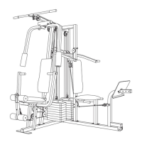
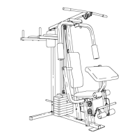
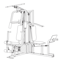
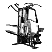
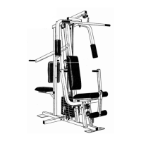
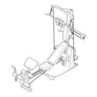
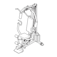
Introduces the WEIDER PRO 9450 and its features.
Specifies the overall height, width, and length of the equipment.
Labels the main parts of the weight system for user familiarity.
Outlines general assembly instructions and required tools.
Details attaching caps to the base and stabiliser.
Connects uprights to the stabiliser and base, adding caps and bumpers.
Attaches the top frame and installs weight bumpers and stacks.
Guides the insertion of weight tubes and top weights into both stacks.
Secures the upper ends of the short and long weight guides.
Attaches the leg press arm to the stabiliser with bushings and bolts.
Connects press arms to the press frame using bolts and nuts.
Installs pulleys and cable traps onto the right and left arms.
Mounts arms onto axles and applies protective padding.
Connects the military press arm to the pivot arm and the pivot arm to the upright.
Locates, unwinds, and identifies cables and pulleys for assembly.
Routes the high cable around a pulley and attaches it to the top frame.
Guides the high cable around a V-pulley on the front upright.
Routes the high cable around pulleys on the left and right arms.
Attaches a pulley bracket to the top frame and routes the high cable.
Attaches the high cable to a long U-bracket with covers.
Routes the high cable around a pulley attached to the top frame.
Connects the high cable to a small U-bracket and weight tube.
Routes the low cable around the pulley on the press frame.
Guides the low cable around pulleys on the front upright.
Routes the low cable around a pulley on the press frame.
Guides the low cable around a second pulley on the front upright.
Visual guide to bolts, screws, nuts, and washers used in assembly.
Visual guide to pulleys, retainers, and plastic bushings.
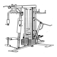
A detailed visual breakdown showing all parts and their assembly relationships.
A detailed list of all parts with key numbers, quantities, and descriptions.
Visual representations of various caps and spacers used in assembly.
Attaches the low cable end to the long U-bracket with specific slack.
Attaches military press cable to a small U-bracket and weight tube.
Wraps military press cable around pulleys and secures to frame/stabiliser.
Routes military press cable around pulleys on the pivot arm and U-bracket.
Guides military press cable around pulley on the leg press upright.
Routes military press cable over another pulley on the leg press upright.
Attaches leg press cable to U-bracket and routes around upright pulley.
Secures leg press cable to the press bracket and seat frame.
Attaches seat plate to backrest and upright, then seat to frame.
Secures the front backrest and attaches the seat to the front seat frame.
Attaches the leg lever and inserts the eyebolt for adjustments.
Slides and secures the front seat frame to the front upright.
Inserts pad tubes and foam pads into the seat frame and leg lever.
Verifies proper cable routing, tension, and smooth operation.
Explains how to change the weight setting using the weight pin.
Describes connecting lat bars and straps to pulley stations.
Guides on attaching and removing the seat for various exercises.
Explains how to adjust and secure the leg press plate for proper function.
Describes using a locking pin to prevent unauthorized use of the system.
A table showing approximate resistance at each exercise station based on weight selection.
Provides methods for tightening cables if slack is detected.
Visual guide for the correct routing of the high and low cables.
Visual guide for the correct routing of military press and leg press cables.
Details how to order replacement parts, including contact info and required details.
| Brand | Weider |
|---|---|
| Model | Pro 9450 |
| Category | Fitness Equipment |
| Language | English |