16
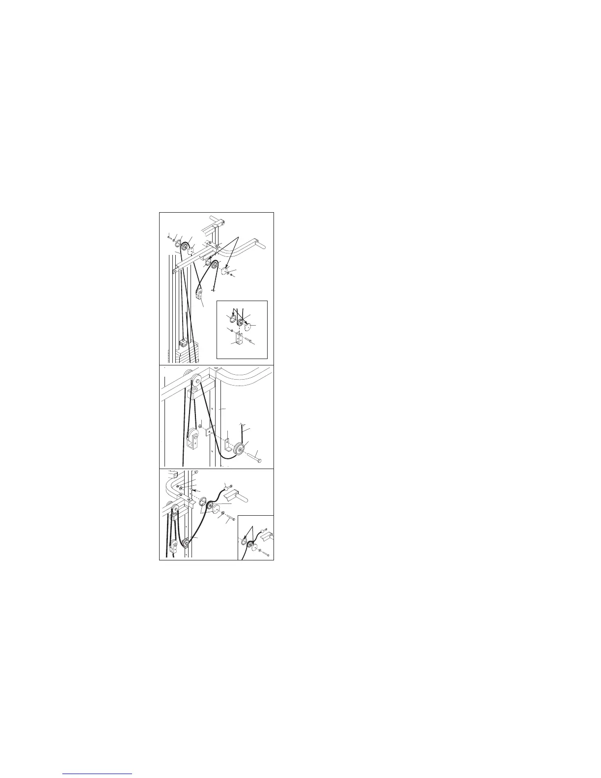
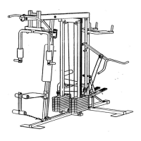
32. Wrap the Military Press Cable (72) around a 3 1/2”
Pulley (15). Attach the Pulley and a pair of Pulley
C
overs (77) to the Pivot Arm (80) with the 3/8”
Washer (9) and the 3/8” x 5 1/4” Bolt (101).
Be
s
ure the Washer and Bolt are on the side
shown, and that the large tabs on the Pulley
Covers are on top. Do not attach a Locknut yet.
See the inset drawing. Wrap the Military Press
Cable (72) around a 3 1/2” Pulley (15). Attach the
Pulley and a pair of Pulley Covers (77) to the upper
hole in the Long “U”-Bracket (57) with a 3/8” x 2”
Bolt (12) and a 3/8” Nylon Locknut (21).
Make sure
the small tabs on the Pulley Covers are on the
side shown. See the inset drawing.
Wrap the Military Press Cable (72) around another
3 1/2” Pulley (15). Attach the Pulley and a pair of
Pulley Covers (77) to the 3/8” x 5 1/4” Bolt (101) on
the other side of the Pivot Arm (80) with a 3/8”
Washer (9) and a 3/8” Nylon Locknut (21).
Be sure
that the Cable is routed as shown. Make sure
the large tabs on the Pulley Covers are on the
side shown. See the inset drawing.
33. Wrap the Military Press Cable (72) around a 3 1/2”
Pulley (15). Attach the Pulley and a Cable Trap (66)
to the Leg Press Upright (56) with a 3/8” x 2” Bolt
(12) and a 3/8” Nylon Locknut (21).
34. Lay the Military Press Cable (72) over a 3 1/2”
Pulley (15). Attach the Pulley and a pair of Pulley
Covers (77) to the Leg Press Upright (56) with a
3/8” x 3 3/4” Bolt (88), two 3/8” Washers (9), and a
3/8” Nylon Jam Nut (99). Make sure the small
tabs on the Pulley Covers are on the side
shown. See the inset drawing.
Make sure that the Military Press Cable (72) is
between the 3 1/2” Pulley (15) and the post. Be
sure that the Cable and Pulley move smoothly.
32
1
01
57
21
77
8
0
15
7
7
77
15
9
77
9
21
57
12
15
77
77
33
56
72
12
15
66
21
34
72
88
9
15
77
56
Post
9
99
72
Small Tabs
Small Tabs
L
arge Tabs