14
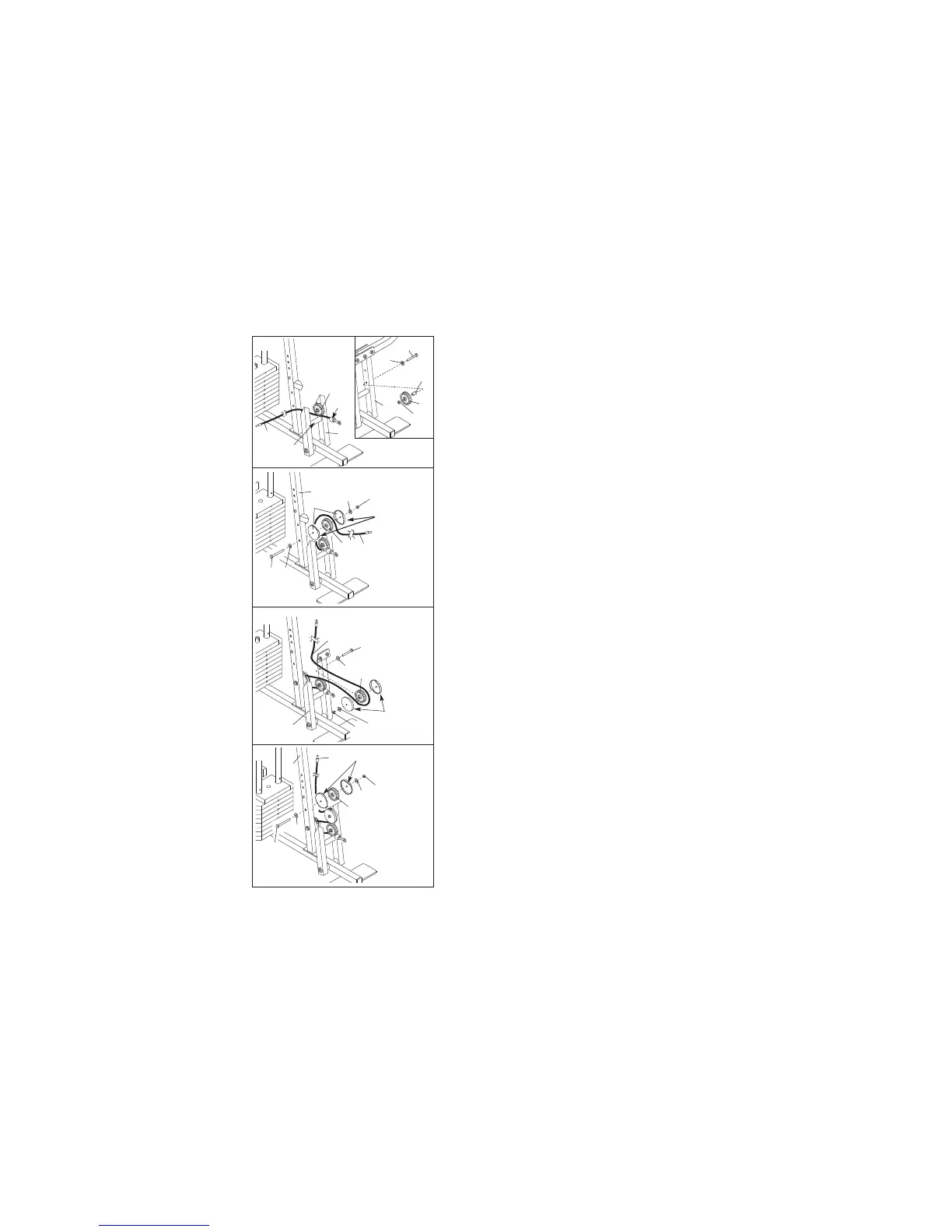
25. Attach the Pulley and the 5/8” x 9/16” Spacer (7) to
the Press Frame (17) with a 3/8” x 3 3/4” Bolt (88),
3
/8” Washer (9), and a 3/8” Nylon Locknut (21). B
e
sure that the parts are oriented as shown in the
d
rawing.
Locate the Low Cable (23) and the bag labelled
“LOW PULLEY.”
Route the Low Cable under the
3 1/2” Low Pulley (76). Be sure that the end of the
Cable with the ball is on the indicated side of
the Press Frame, between the Pulley and the
crossbar.
26. Route the Low Cable (23) around a 3 1/2” Pulley
(15). Attach the Pulley, a set of Pulley Covers (77),
and two 3/8” Washers (9) to the lower hole in the
Front Upright (42) with a 3/8” Nylon Jam Nut (99)
and a 3/8” x 3 3/4” Bolt (88). Be sure the small
tabs on the Pulley Covers are in the indicated
position.
27. Route the Low Cable (23) around a 3 1/2” Pulley
(15). Attach the Pulley, a set of Pulley Covers (77),
and two 3/8” Washers (9) to the upper hole in the
Press Frame (17) with a 3/8” Nylon Locknut (21)
and a 3/8” x 3 1/2” Bolt (16). Be sure that the
large tabs on the Pulley Covers are in the posi-
tion shown.
28. Route the Low Cable (23) around another 3 1/2”
Pulley (15).
Attach the Pulley, a set of Pulley
Covers (77), and two 3/8” Washers (9) to the upper
hole in the Front Upright (42) with a 3/8” Nylon Jam
Nut (99) and a 3/8” x 3 3/4” Bolt (88).
Be sure the
small tabs on the Pulley Covers are in the indi-
cated position.
2
1
17
76
7
9
8
8
23
17
Ball
76
Crossbar
2
5
23
99
9
Small tabs
should be here.
88
9
15
42
77
26
23
9
16
17
77—Large
tabs should
be here.
15
9
21
27
77—Small tabs
should be here.
23
15
42
99
9
88
9
28