ASSEMBLY
5
1
2
88
4
82
Bracket
Low Side
14
88
5
3
8
3
11
86
8
11
3
20
4
1
27
1
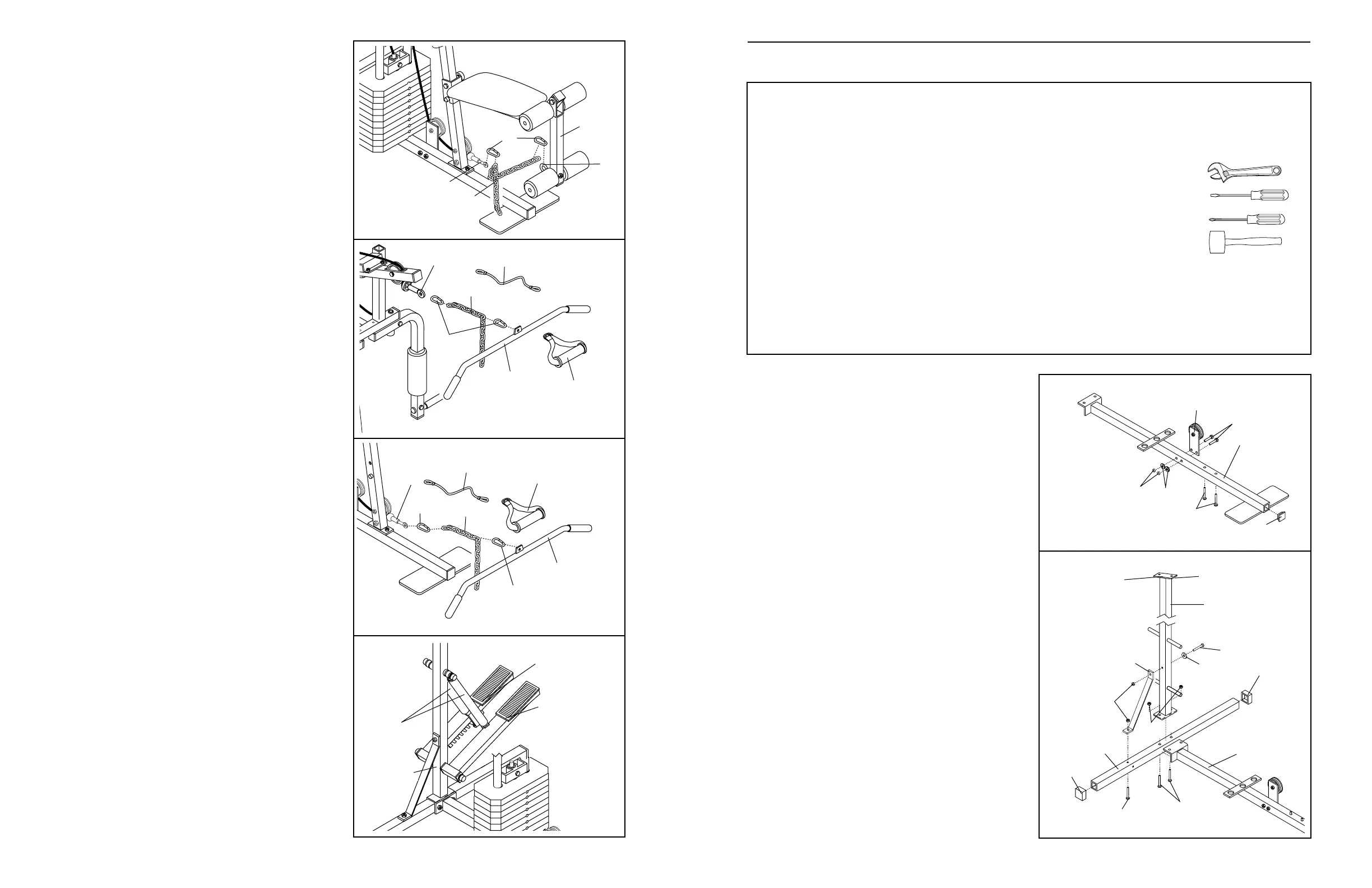
Before beginning assembly, carefully read the
following information and instructions:
• Place all parts of the weight system in a cleared
area and remove the packing materials; do not
dispose of the packing materials until assembly is
completed.
• Read each assembly step before you begin.
• For help identifying the small parts used in
assembly, use the PART IDENTIFICATION
CHART located in the centre of this manual.
Note: Some small parts may have been pre-
attached for shipping purposes. If a part is not in
the parts bag, check to see if it has been pre-
attached.
• As you assemble the weight system, be sure that
all parts are oriented as shown in the drawings.
• Tighten all parts as you assemble them, unless
instructed to do otherwise.
THE FOLLOWING TOOLS (NOT INCLUDED) ARE
REQUIRED FOR ASSEMBLY:
• Two adjustable spanners
• One standard screwdriver
• One phillips screwdriver
• One rubber mallet
• Lubricant, such as grease or petroleum jelly,
and soapy water will also be needed.
Assembly will be more convenient if you have the
following tools: A socket set, a set of open-end or
closed-end wrenches, or a set of ratchet wrenches.
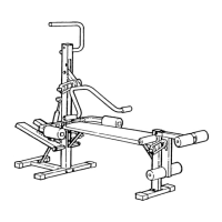
1. Before you begin, make sure that you have
carefully read the instructions at the top of
this page.
Press a 2” Inner Cap (27) into the Base (4).
Attach the Pulley Plate (20) to the Base (4) with
two 5/16” x 2 3/4” Bolts (11), two 5/16” Flat
Washers (8), and two 5/16” Nylon Locknuts (3).
Insert the two 5/16” x 2 1/2” Carriage Bolts (1) up
through the Base (4).
2. Press the two 2” Outer Caps (88) onto the
Stabiliser (5).
Insert two 5/16” x 2 3/4” Carriage Bolts (14) and
one 5/16” x 2 1/2” Carriage Bolt (1) up through
the Stabiliser (5). Slide the end of the Base (4)
and the Rear Upright (82) onto the two 5/16” x
2 3/4” Carriage Bolts (14). Make sure that the
Rear Upright is turned as shown. Thread 5/16”
Nylon Locknuts (3) onto the two Carriage Bolts.
Do not tighten the Nylon Locknuts yet.
Slide one end of the Brace (86) onto the 5/16” x
2 1/2” Carriage Bolt (1) in the Stabiliser (5). Thread
a 5/16” Nylon Locknut (3) onto the Carriage Bolt.
Do not tighten the Nylon Locknut yet.
Attach the other end of the Brace (86) to the Rear
Upright (82) with a 5/16” x 2 3/4” Bolt (11), a 5/16”
Flat Washer (8), and a 5/16” Nylon Locknut (3).
Do not tighten the Nylon Locknut yet.
16
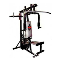
ATTACHING THE LEG LEVER TO THE LOW
PULLEY STATION
To use the Leg Lever (29), the seat must be attached
to the front upright (see ATTACHING AND REMOV-
ING THE SEAT on page 15).
Attach the Chain (84) between the 3/8” x 2” Eyebolt
(62) on the Leg Lever (29) and the Short Cable (23)
with two Cable Clips (83).
ATTACHING THE LAT BAR OR NYLON STRAP TO
THE HIGH PULLEY STATION
Attach the Lat Bar (85) to the Long Cable (66) with a
Cable Clip (83). For some exercises, the Chain (84)
and/or Nylon Rope (76) should be attached between
the Lat Bar and the Long Cable with two Cable Clips.
If the Chain is used, adjust the length of the Chain
between the Lat Bar and the Long Cable so the
Lat Bar is in the correct starting position for the
exercise to be performed.
The Nylon Strap (39) can be attached in the same way.
ATTACHING THE LAT BAR OR NYLON STRAP TO
THE LOW PULLEY STATION
Attach the Lat Bar (85) to the Short Cable (23) with a
Cable Clip (83). For some exercises, the Chain (84)
and/or Nylon Rope (76) should be attached between
the Lat Bar and the Short Cable with two Cable Clips.
If the Chain is used, adjust the length of the Chain
between the Lat Bar and the Short Cable so the
Lat Bar is in the correct starting position for the
exercise to be performed.
The Nylon Strap (39) can be attached in the same way.
CHANGING THE STEPPING RESISTANCE
To change the stepping resistance, first lift the Right
and Left Pedals (89, 90) off the hooks at the lower
ends of the Resistance Cylinders (91). Move the
hooks to different slots under the Pedals. Make sure
that the hooks are fully inserted into the slots in
the same position under both Pedals. The farther
the hooks are moved from the Rear Upright (82), the
greater the resistance will be. CAUTION: The
Resistance Cylinders become very hot during use.
Allow the Resistance Cylinders to cool before
touching them.
39
39
66
83
76
84
85
85
23
83
83
84
76
89
90
91
82
83
84
23
29
62
 Loading...