14
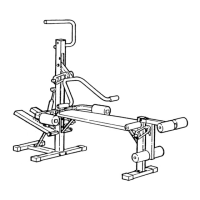
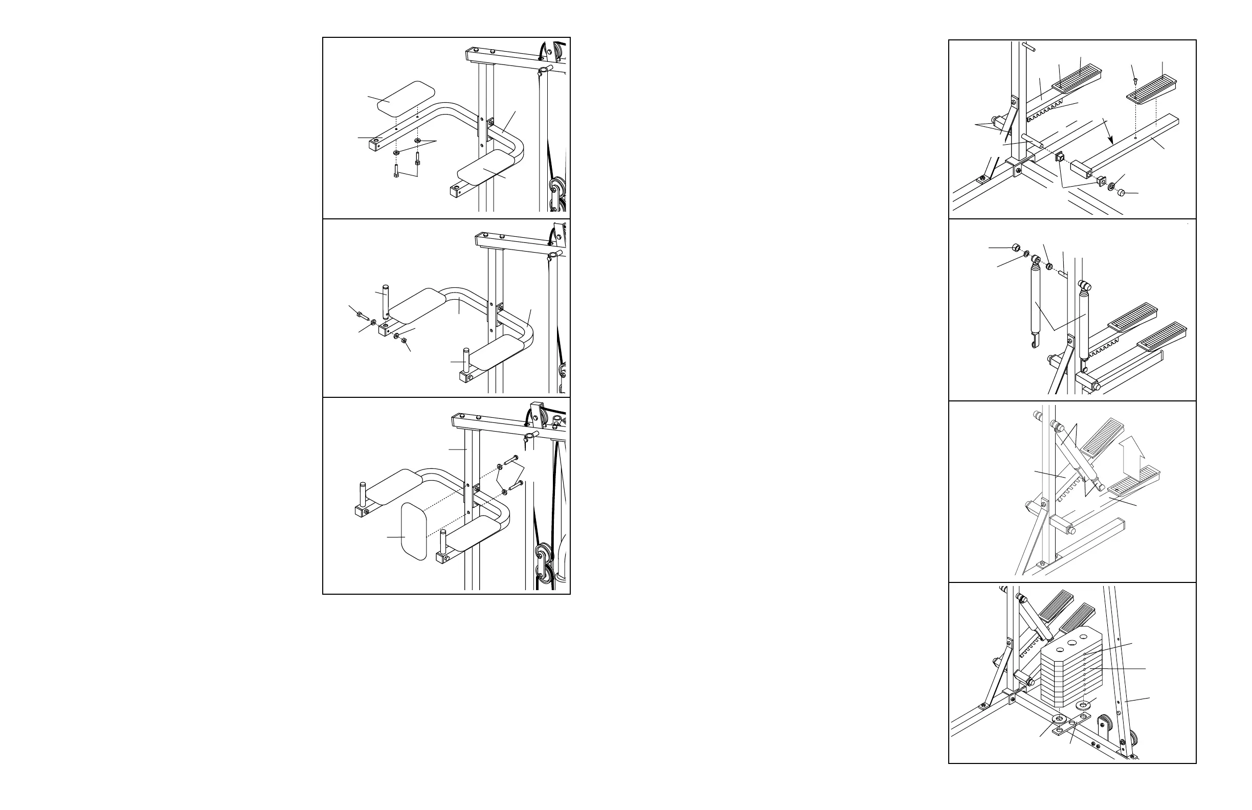
30. Attach a VKR Armrest (99) to the Right VKR Arm
(101) with two 1/4” x 2” Screws (102) and 1/4”
Flat Washers (10).
Attach a VKR Armrest (99) to the Left VKR Arm
(100) in the same manner.
31. Insert a 7” Handle (47) into the Right VKR Arm
(101). Attach the Handle with a 5/16” x 2” Bolt
(61), two 5/16” Flat Washers (8), and a 5/16”
Nylon Locknut (3).
Attach the other 7” Handle (47) to the Left VKR
Arm (100) in the same manner.
32. Attach the VKR Backrest (98) to the Rear Upright
(82) with two 1/4” x 2 1/2” Screws (43) and two
1/4” Flat Washers (10).
30
31
32
99
101
100
10
102
99
61
8
8
3
101
100
47
47
98
82
10
43
33. Make sure that all parts are properly tightened. The use of all remaining parts will be explained in ADJUST-
MENT, beginning on page 15 of this manual. Before using the weight system, pull each cable a few times to
make sure that the cables move smoothly over the pulleys. If one of the cables does not move smoothly,
locate and correct the problem before using the weight system. IMPORTANT: If the cables are not proper-
ly routed, they may be damaged when heavy weight is used. See the CABLE DIAGRAM on page 19
of this manual.
7
5. Press two 1 1/2” Bushings (93) into the Left Pedal
(90); press two 1 1/2” Bushings (93) into the
Right Pedal (89). Attach a Pedal Cover (92) to
each Pedal with a 1/2” Tap Screw (6).
Lubricate the pedal axles on the Rear Upright
(82). Slide the Right and Left Pedals (89, 90) onto
the right and left pedal axles. Note: Make sure
that the Pedals are on the correct sides; the
slotted brackets must be on the insides of the
Pedals. Hold a 1" Retainer (54) and 1" Round
Cover Cap (55) against the left pedal axle. The
teeth on the Retainer must bend toward the
Round Cover Cap. Tap the Retainer and Round
Cover Cap onto the pedal axle. Attach the Right
Pedal in the same manner.
6. Lubricate the cylinder axles on the Rear Upright
(82). Slide a 5/8” Spacer (97) and a Resistance
Cylinder (91) onto the right cylinder axle. Be sure
that the Spacer is turned as shown. Hold a 5/8"
Retainer (95) and 5/8" Round Cover Cap (96)
against the right cylinder axle. The teeth on the
Retainer must bend toward the Round Cover
Cap. Tap the Retainer and Round Cover Cap
onto the cylinder axle.
Attach a Resistance Cylinder (91) to the left cylin-
der axle in the same manner.
7. Raise the Left Pedal (90) and rest it on the hook
at the lower end of the left Resistance Cylinder
(91). The hook must be in one of the slots under
the Left Pedal.
Raise the Right Pedal (89) and rest it on the hook
at the lower end of the right Resistance Cylinder
(91). Make sure that the hooks are in the same
position under both Pedals.
8. Set the two Weight Bumpers (19) on the indicated
plate on the Base (4). Align the holes in the
Weight Bumpers with the holes in the plate.
Stack nine Weights (25) on the Weight Bumpers
(19). Each Weight must be turned so the pin
groove is facing the Front Upright (42). The
holes in the Weights must be aligned with the
holes in the Weight Bumpers. CAUTION: Be
careful to avoid tipping the stack of Weights
until step 9 is completed.
7
5
6
92
92
6
6
55
54
90
89
96
95
91
97
82—Lubricate
91
90
89
Hooks
82
Lubricate
93
93
8
19
19
4
25
42
Pin Groove
Slotted
Brackets
 Loading...