13
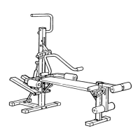
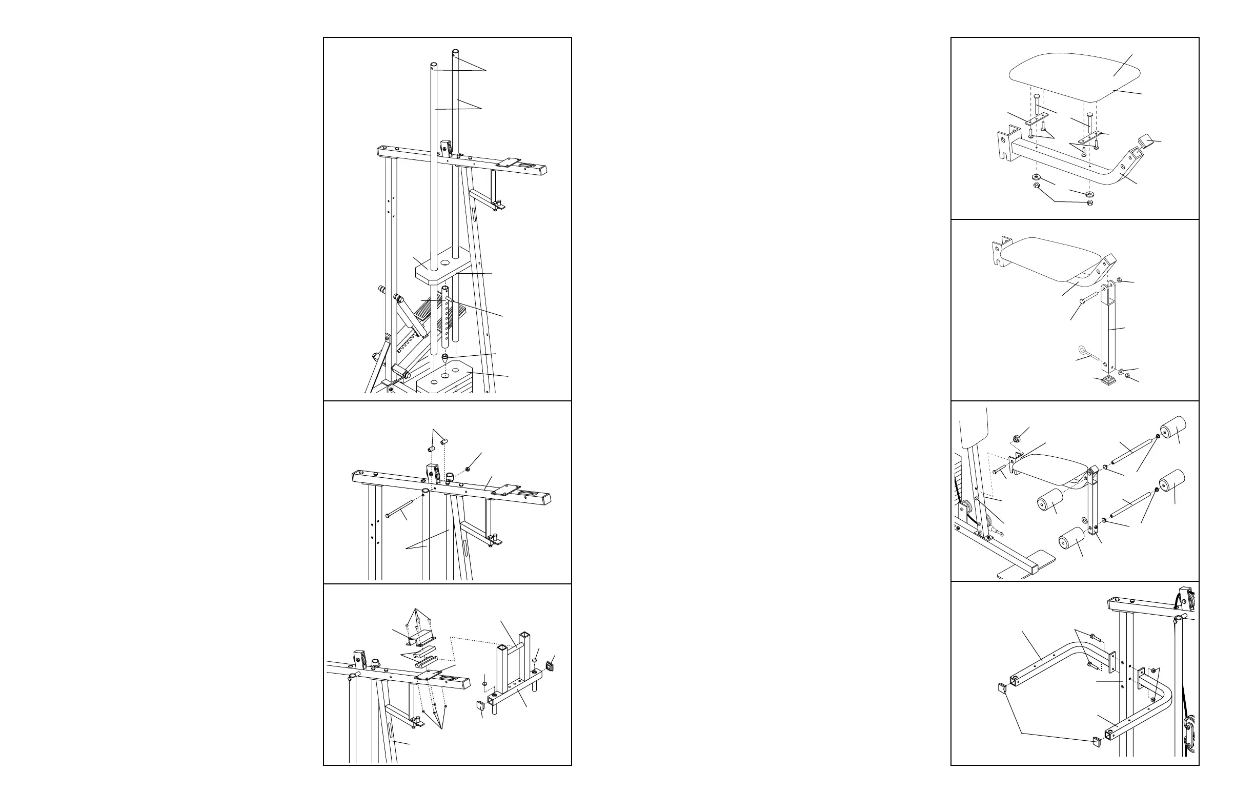
26. Press a 1 1/2” Inner Cap (32) into the Seat Frame
(36).
Insert a 1/4” x 2” Carriage Bolt (38) into the centre
of each Seat Plate (37). Attach the Seat Plates to
the Seat (13) with four 1/4” x 3/4” Screws (18).
Insert the two 1/4” x 2” Carriage Bolts (38) into
the Seat Frame (36). Make sure that the Seat
(13) is turned so the wide end is toward the
1 1/2” Inner Cap (32). Tighten a 1/4” Nylon
Locknut (7) with 1/4” Flat Washer (10) onto each
Carriage Bolt.
27. Press a 1 1/2” Inner Cap (32) into the Leg Lever
(29).
Attach the 3/8” x 2” Eyebolt (62) to the Leg Lever
(29) with a 3/8” Flat Washer (9) and a 3/8” Nylon
Locknut (21).
Lubricate a 5/16” x 2 1/4” Bolt (33). Attach the
Leg Lever (29) to the Seat Frame (36) with the
Bolt and a 5/16” Nylon Locknut (3). Do not over-
tighten the Nylon Locknut; the Leg Lever
must be able to pivot freely.
28. Set the bracket on the Seat Frame (36) onto the
indicated pins on the Front Upright (42). Attach
the Seat Frame with a 5/16” x 2 3/4” Carriage
Bolt (14) and the Seat Knob (40).
Press 3/4” Round Inner Caps (34) into the ends
of the 13 1/2” Pad Tube (28). Insert the Pad Tube
into the Seat Frame (36). Slide a 6” Pad (30) onto
each end of the Pad Tube.
Press 3/4” Round Inner Caps (34) into the ends
of the 13” Pad Tube (31). Insert the Pad Tube into
the Leg Lever (29). Slide a 5 1/2” Pad (50) onto
each end of the Pad Tube.
29. Press 1 1/2” Inner Caps (32) into the Left and
Right VKR Arms (100, 101).
Attach the Left and Right VKR Arms (100, 101) to
the Rear Upright (82) with two 5/16” x 2 3/4” Bolts
(11) and 5/16” Nylon Locknuts (3).
29
101
100
82
11
32
3
13
Wide
End
32
7
29
21
9
62
3
33—Lubricate
32
31
28
29
50
30
30
36
40
14
42
Pin
50
34
34
36
18
10
37
36
38
37
26
27
28
8
9
10
11
79
Pin
Groove
Welded Pin
80
72
Upper Ends of
Weight Guides
have Holes
25
25
72
67
74
73
3
44
68
67
49
49
42
69
7
18
44
Lubricate
52
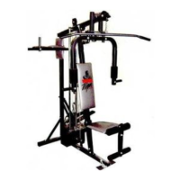
9. Press the Weight Tube Endcap (79) into the indi-
cated end of the Weight Tube (80).
Insert the Weight Tube (80) into the stack of
Weights (25). Slide the tenth Weight (25) onto the
upper end of the Weight Tube. The Weight Tube
must be turned so the welded pin is in the pin
groove in the Weight.
Locate the lower ends of the Weight Guides (72)
(there are holes near the upper ends). Insert the
lower ends of the Weight Guides into the ten
Weights (25).
10. Attach the upper ends of the Weight Guides (72)
to the Top Frame (67) with the 5/16” x 6” Bolt
(74), the two 1/2” x 3/4” Bushings (73), and a
5/16” Nylon Locknut (3).
11. Press two 1 3/4” Inner Caps (44) and two 1”
Round Inner Caps (49) into the Arm Frame (52).
Lubricate the upper axle on the Arm Frame (52).
Hold the axle between the two Arm Frame
Bushings (68). Set the Arm Frame Bushings and
the Arm Frame on the welded plate on the Top
Frame (67). Place the Arm Frame Bracket (69)
over the Arm Frame Bushings. Attach the Arm
Frame Bracket to the Top Frame with four 1/4” x
3/4” Screws (18) and 1/4” Nylon Locknuts (7).
 Loading...