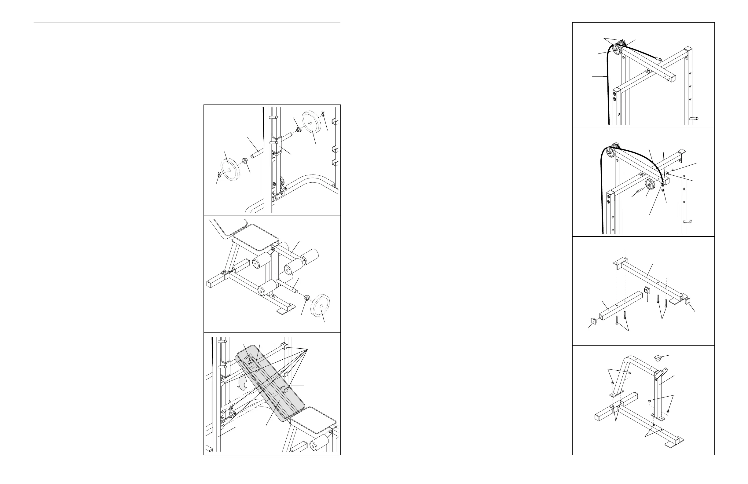
9
9. Route the Cable (51) around the indicated Pulley
(24). Tighten the M10 Nylon Locknut (2) and the
M10 x 120mm Bolt (not shown). Do not overtighten
the Nylon Locknut. Be sure that both Cable
Traps (23) are turned as shown and that the
Cable and Pulleys move smoothly.
10. Wrap the Cable (51) around a Pulley (24). Attach
the Pulley to the Top Frame (21) with an M10 x
89mm Bolt (9), an M10 Washer (10), and an M10
Nylon Locknut (2). Be sure that the cable stop is
on the indicated side of the Pulley and that the
Cable is between the Pulley and the welded
post.
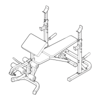
11. Press a 2” Square Inner Cap (46) into each end of
the Stabilizer (33). Press a 2” Square Inner Cap
(46) into the end of the Bench Base (43).
Insert two M8 x 60mm Carriage Bolts (3) up
through the Stabilizer (33). Slide the end of the
Bench Base (43) onto the Carriage Bolts.
Insert two M8 x 60mm Carriage Bolts (3) up
through the Bench Base (43).
12. Slide the Bench Frame (49) onto the M8 x 60mm
Carriage Bolts (3). Tighten an M8 Nylon Locknut (4)
onto each Carriage Bolt.
Press a 2” Square Inner Cap (46) into the Bench
Frame (49).
12
9
2
24
23
2
10
21
24
51
9
51
10
11
46
46
43
46
33
3
4
4
3
3
49
46
3
12
BIJSTELLEN VAN DE PRO 355
De gewichtsbank is ontworpen om u de gelegenheid te geven om uw eigen gewichten te gebruiken. De volgen-
de stappen leggen u uit hoe u de bank kunt bijstellen. Zie ADVIES VOOR HET OEFENEN op pagina 9 voor
belangrijke informatie. Lees ook de bijgaande informatie van uw eigen gewichten (niet inbegrepen) voor nog
meer oefeningen.
Inspecteer voor elk gebruik de bank en draai alle onderdelen vast. Vervang gesleten onderdelen meteen. U kunt
de bank schoonmaken met een vochtige doek en een zacht schoonmaakmiddel. Gebruik geen schuurmiddel.
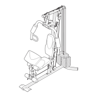
ATTACHING WEIGHTS TO THE WEIGHT CARRIAGE
To use the high or low pulley station, first slide a Weight
Stop (35) onto each side of the weight tube of the Weight
Carriage (52). Slide the desired amount of weight (not
included) onto the weight tube. Be sure that an equal
amount of weight is on each side of the weight tube.
Secure the weights on each side of the weight tube with a
Spring Clip (44).
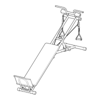
ATTACHING WEIGHTS TO THE LEG LEVER
To use the Leg Lever (32), be sure there is a Weight Stop
(35) on the weight tube. Then slide the desired amount of
weight (not included) onto the weight tube.
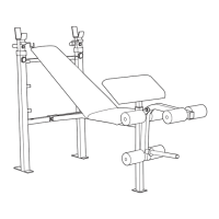
ADJUSTING THE BACKREST
The Backrest (29) can be set at three different positions:
the level position, the decline position, and the incline posi-
tion.
To change the position of the Backrest (29), move the
Adjustment Tube (31) to a different set of adjustment
brackets on the Left and Right Uprights (18, 19). Make
sure that the Adjustment Tube is securely seated in
the adjustment brackets and that it is also firmly
seated in one of the slots in the Adjustment Backrest
Bracket (26).
Gewicht
Gewicht
Gewichtsbuis
Cable
Stop
Welded
Post
44
44
35
52
32
31
26
18
19
Slots
Adjustment
Brackets
35
Gewichtsbuis
29
Gewicht
35