13
ATTACHING THE LAT BAR OR NYLON STRAP TO
THE HIGH PULLEY STATION
Attach the Lat Bar (36) to the Cable (51) with a Cable
Clip (45).
The Nylon Strap (27) can be attached in the same man-
ner.
ATTACHING THE LAT BAR OR NYLON STRAP TO
THE LOW PULLEY STATION
Attach the Lat Bar (36) to the Cable (51) with a Cable
Clip (45).
The Nylon Strap (27) can be attached in the same man-
ner.
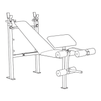
SETTING THE ADJUSTMENT WEIGHT RESTS
To perform squat exercises or toe raise exercises (see
the accompanying EXERCISE POSTER) you will need
to set the Adjustment Weight Rests (37) to a comforta-
ble height.
Insert the Adjustment Weight Rests (37) into the adjust-
ment holes at the desired height. Be sure that each
Adjustment Weight Rest is firmly seated in the
adjustment hole and that both Adjustment Weight
Rests are at the same height.
8
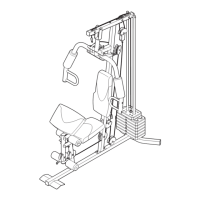
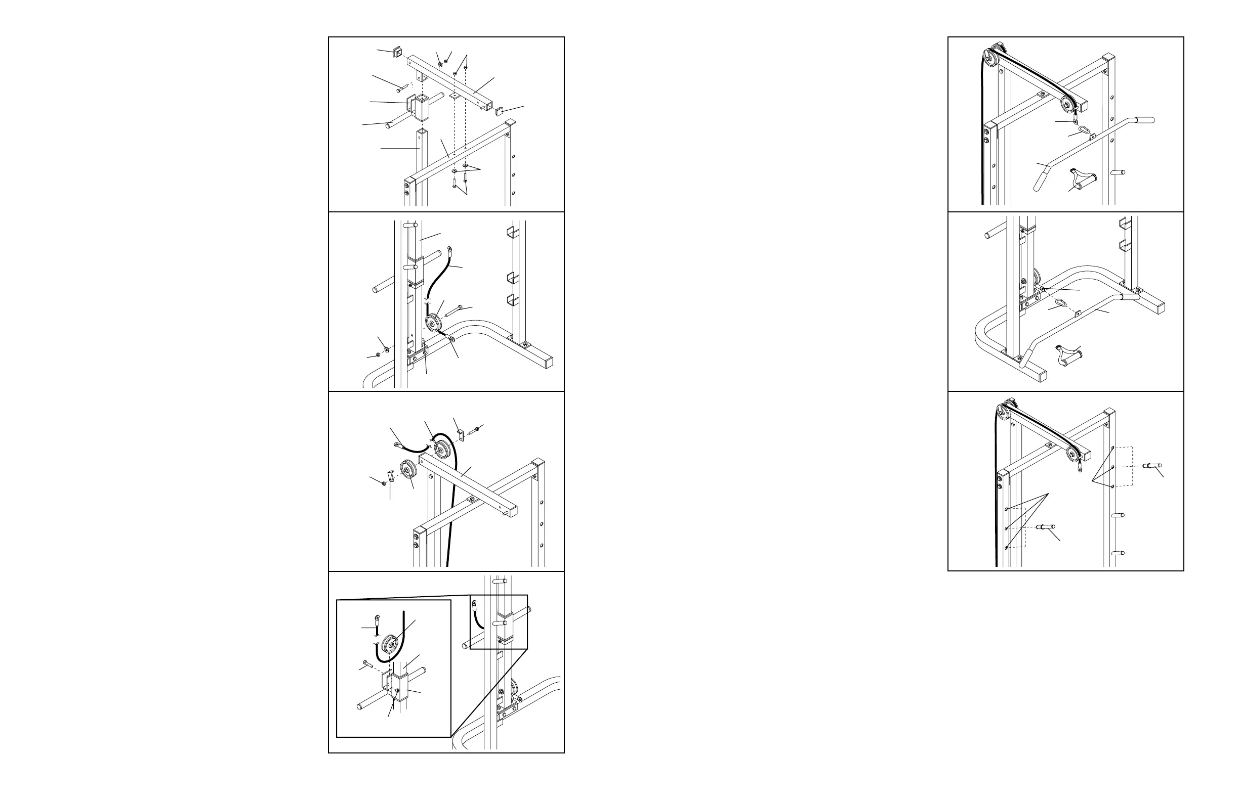
5. Slide the Weight Carriage (52) onto the Main
Upright (42). The bracket must be on the side
shown.
Press a 2” Square Inner Cap (46) into each end of
the Top Frame (21). Attach the Top Frame to the
Main Upright (42) with an M8 x 68mm Bolt (8), an
M8 Washer (13), and an M8 Nylon Locknut (4).
Attach the Top Frame (21) to the Crossbar (22) with
two M8 x 68mm Bolts (8), two M8 Washers (13),
and two M8 Nylon Locknuts (4).
Tighten all Nylon Locknuts and Bolts used in
steps 1–5 now.
6. Wrap the Cable (51) around a Pulley (24). Attach
the Pulley to the Main Upright (42) with an M10 x
89mm Bolt (9), an M10 Washer (10), and an M10
Nylon Locknut (2). Be sure that the cable stop is
on the indicated side of the Pulley and that the
Cable is between the Pulley and the welded
post.
7. Attach two Pulleys (24) and two Cable Traps (23) to
the Top Frame (21) with an M10 x 120mm Bolt (12)
and an M10 Nylon Locknut (2). Do not tighten the
Nylon Locknut yet.
Route the Cable (51) around the indicated Pulley
(24) from the direction shown. Be sure that the
Cable is between the Pulley and the Cable Trap
(23).
8. Wrap the Cable (51) around a Pulley (24). Attach
the Pulley to the Weight Carriage (52) with an M10
x 43mm Bolt (11) and an M10 Nylon Locknut (2).
The Cable must be routed around the Pulley
from the direction shown.
8
5
4
4
13
8
Bracket
8
52
42
21
22
13
46
46
24
9
10
2
42
2
23
24
24
51
21
12
6
7
51
45
36
27
51
45
36
27
37
51
23
24
51
52
11
2
42
Cable Stop
Welded Post
Adjustment
Holes
37