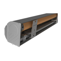
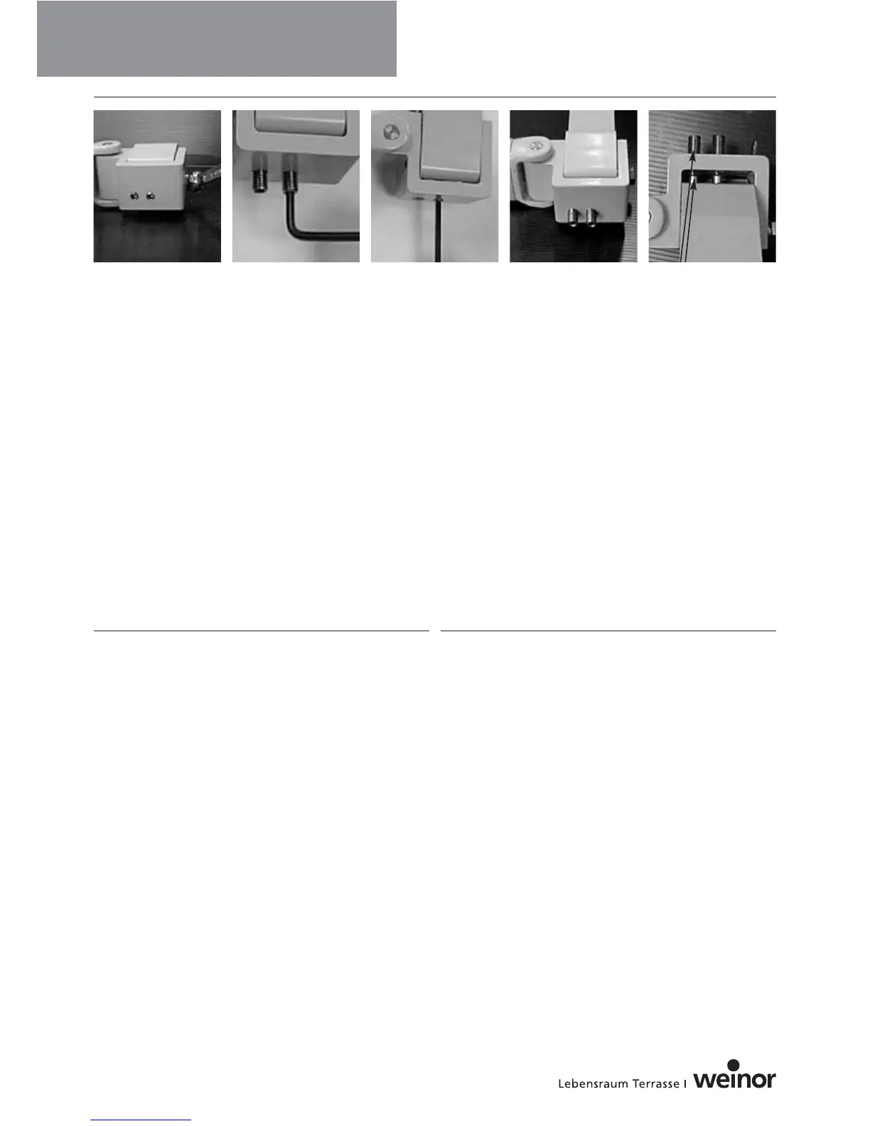
Neigungsverstellung Topas mit und ohne Dach
• Klemmschraube (M10) am Kippteil lösen (Pict 5).
• Verstellen der Neigung:
Beide Gewindestifte M10 drehen.
Hereindrehen: Neigung wird flacher (Pict 6).
Herausdrehen: Neigung wird steiler.
Die Klemmschraube muss mit einem Drehmoment von 70 Nm
angezogen werden, um den höchsten Widerstand gegen die
Windkraft zu erreichen. Überprüfen Sie, ob beide Verstellschrau-
ben am Schubträger anliegen (Pict 9).
Die Verstellschrauben dürfen maximal bündig mit dem Kippteil
hereingeschraubt werden (Pict 7).
Das Herausschrauben darf nur soweit erfolgen, dass noch alle
Gewindegänge des Kippteils die Verstellschrauben tragen (Pict 8).
Ansicht des Schubträgers von unten gesehen (Pict 9):
Die Stellschrauben sind auf den Maximalwert herausgedreht.
Der letzte Gewindegang ist hier noch zu erkennen.
㛯㛯㛯
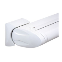
Einstellung der Kassettenneigung der Cassita
Das Abnehmen der Abdeckkappen ist für das Verstellen der
Kassettenneigung nicht nötig. Den Innensechskantschlüssel (SW 8)
wie dargestellt ansetzen (Pict 10) und entsprechend der gewünsch-
ten Neigung drehen. Dies ist schrittweise auf beiden Seiten
abwechselnd durchzuführen.
Pict 5 Pict 6 Pict 7 Pict 8 Pict 9
Angle Adjustment Mechanism for Topas with and without hood
• Loosen the clamping nut (M10) on the tilting arm member (Pict 5).
• Adjusting the Pitch:
Turn both setscrews M10.
If turned inwards, the pitch becomes shallower (Pict. 6)
If turned outwards, the pitch becomes sharper
Tighten the locking screw to a torque of 70 Nm to ensure the
mechanism has the greatest resistance to the wind force.
Check that the two adjusting screws are resting against the
thrust support (Pict 9).
The adjusting screws must, at the very most, be screwed in only
as far as to lie flush with the tilting arm member (Pict 7).
Only unscrew the unit when it is certain that all of the threads on
the tilting arm member can support the adjusting screws (Pict. 8).
View of the bracket from below (Pict. 9):
The adjusting screws have been loosened as far as permissible.
The last of the thread can still be seen here.
㛯㛯㛯
Cassette Pitch Adjustment for Cassita
To adjust the pitch it is not necessary to remove the caps. Apply
the Allen key (SW 8) as shown in Pict. 10 and turn to the required
pitch. This should be performed gradually and alternately on both
sides.
Wichtige Information
Important Information
㛯㛯㛯
8
Gelenkarmmarkisen