30
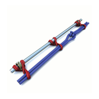
Figure 3. Additional Spines in Place of Anchor Crossover
Assemblies Shown. For clarity purposes, the main line Spine and
Ribs (shown in Figure 2) are not shown here.
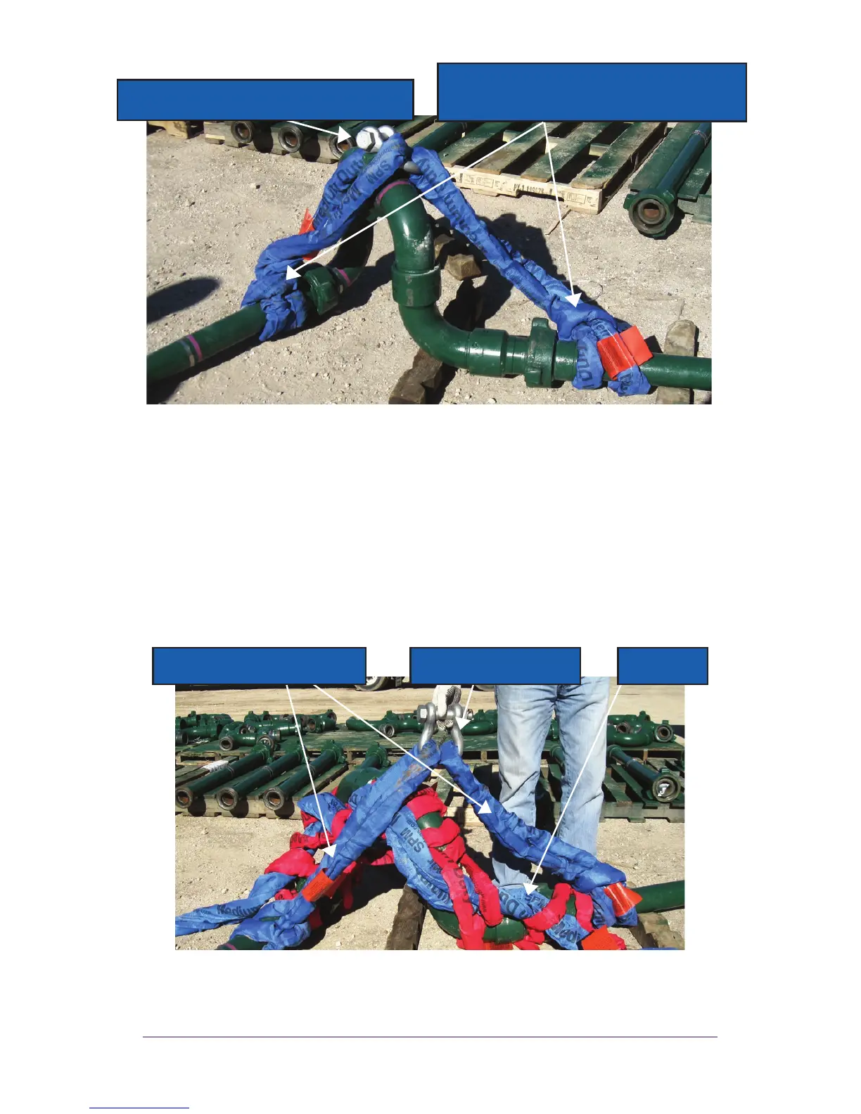
3. Figure 4 shows the complete, final assembly. The main Spine
and Ribs are installed with two additional Spines to replace the
Anchor Crossovers. The two additional Spines are connected using
a “C-type” shackle.
Figure 4. Final Set Up
Install two additional spines in place of
anchor crossovers and loop around the
straight section of the pipe
“Anchor” type (or “C” type) shackle to
connect the two additional Spines
Shackle to connect two
additional spines
Main Spine
and Ribs
Additional Spines installed
and connected with a Shackle