33
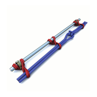
Figure 6. SPM
®
FSR Connection Loops
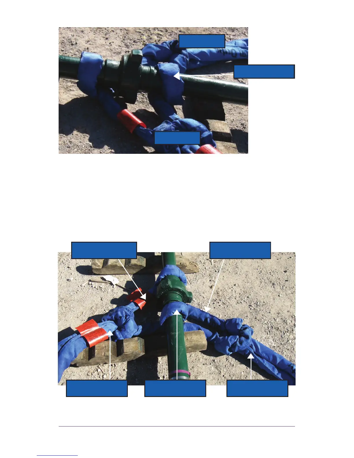
3. Install the Left and Right SPM
®
FSR Anchor Lines as shown in
Figure 7. Follow the looping procedure referenced in the following
section. Loop the SPM
®
FSR Spine 2 to the Left Connection Loop
and pull until the knot is taut. Loop SPM
®
FSR Spine 3 to the Right
Connection Loop and pull until the knot is taut. It is key that all
SPM
®
FSR components are pulled taut throughout the assembly.
Figure 7. Final Set Up with SPM
®
FSR Anchor Lines
END “B”
END “A”
SPM
®
FSR Spine 1
SPM
®
FSR Spine 1
(Connection Loop)
SPM
®
FSR
Spine 3
(Right Anchor Line)
SPM
®
FSR Spine 2
(Left Anchor Line)
Left Connection Loop
(END “A”)
Right Connection
Loop (END “B”)