This document is an Operation Instruction and Service Manual for the SPM® EXL Pressure Relief Disc, a product designed for well service pumps and flow control applications. It provides comprehensive information regarding the device's function, technical specifications, usage, and maintenance.
Function Description
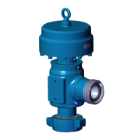
The SPM® EXL Pressure Relief Disc is an overpressure relief device designed to provide an additional layer of protection for personnel and equipment during pumping operations, especially when used in conjunction with SPM® Nitrogen or Spring Relief valves. Its primary function is to rupture and discharge pressurized fluids in the event of an overpressure event, thereby preventing damage to equipment and ensuring safety. The disc is replaceable, allowing for flexibility in pressure ratings and reducing replacement costs. It is engineered to provide controlled discharge within a small tolerance band of the desired rupture rating.
Important Technical Specifications
The manual covers two main housing assemblies:
- 2" 1502 Housing Assembly (Part Number: 2A42318)
- 3" 1502 Housing Assembly (Part Number: 2A42229)
A variety of rupture disc kits are available, categorized by size and burst pressure:
For 2"-1502 Housing:
- KIT/RUPTURE DISC/2-1502/6,000 PSI (2A42604)
- KIT/RUPTURE DISC/2-1502/10,500 PSI (2A42605)
- KIT/RUPTURE DISC/2-1502/12,500 PSI (2A42606)
- KIT/RUPTURE DISC/2-1502/14,500 PSI (2A42607)
- KIT/RUPTURE DISC/2-1502/15,000 PSI (2A42540)
- KIT/RUPTURE DISC/2-1502/15,500 PSI (2A42772)
For 3"-1502 Housing:
- KIT/RUPTURE DISC/3-1502/6,000 PSI (2A42600)
- KIT/RUPTURE DISC/3-1502/10,500 PSI (2A42601)
- KIT/RUPTURE DISC/3-1502/12,500 PSI (2A42602)
- KIT/RUPTURE DISC/3-1502/14,500 PSI (2A42603)
- KIT/RUPTURE DISC/3-1502/15,000 PSI (2A42539)
- KIT/RUPTURE DISC/3-1502/15,500 PSI (2A42781)
The rupture discs are machined from a single piece of Hastelloy 276, ensuring superior corrosion resistance and improved repeatability. Each integral union connection is clearly marked with a pressure code (e.g., "1502", 15,000 PSI), which must not be exceeded and should be matched with mating unions of the same size and pressure rating.
The relief tolerance for the disc is +/- 5% of the rated disc pressure. The lowest rupture disc pressure available is 2500 PSI.
Bill of Materials (BOM) for 2"-1502 Version (2A42318):
- Wing Nut (3P10228) - QTY 2
- Retainer Segments (3P10231) - QTY 3
- Retainer Ring (P10232) - QTY 1
- Hex Nut (2P43556) - QTY 1
- Nord-Loc Washer (Reference Kit part numbers on page 5) - QTY 1
- Rupture Disc (Reference Kit part numbers on page 5) - QTY 1
- Rupture Disc O-Ring (2P43555) - QTY 1
- Rupture Disc Body (4P10229) - QTY 1
- Seal (2P43730) - QTY 1
- Disc Catcher (2P43730) - QTY 1
Bill of Materials (BOM) for 3"-1502 Version (2A42229):
- Wing Nut (2P41604) - QTY 2
- Retainer Segments (3P10260) - QTY 3
- Retainer Ring (P10261) - QTY 1
- Hex Nut (2P43558) - QTY 1
- Nord-Loc Washer (Reference Kit part numbers on page 5) - QTY 1
- Rupture Disc (Reference Kit part numbers on page 5) - QTY 1
- Rupture Disc O-Ring (2P43557) - QTY 1
- Rupture Disc Body (4P10258) - QTY 1
- Seal (2P43729) - QTY 1
- Disc Catcher (2P43729) - QTY 1
The device is designed to discharge atmospherically when it relieves. It includes a disc catcher for containing ejected debris, though the catcher can be removed for applications requiring plumbing to a containment vessel.
Usage Features
The SPM® EXL Pressure Relief Disc is designed for easy installation and operation. The in-line housing (MxF) allows for straightforward installation on fluid ends or within treating iron lines. The design facilitates correct installation orientation of all components, with the rupture disc having an etched "FLOW" arrow indicating the direction of fluid flow.
Installation Process:
- Liberally coat the O-ring with Super Lube lubricant or equivalent and install it into the groove.
- Install the rupture disc with the correct orientation (following the "FLOW" etching).
- Install the Lock Washer.
- Apply anti-seize on the hex nut threads.
- Tighten the Hex Nut using an SPM® Tool (PN: 2P43174 for 2" or 2P43175 for 3") to 75 ft. lbs.
- Apply the Burst Pressure Label (2P42811) onto the housing.
- For the rupture disc catcher, position it onto the threaded side of the rupture disc assembly.
- Tighten the wing nut by hand to engage threads, then use a hammer to fully tighten the catcher onto the assembly.
Operational Considerations:
- The device is suitable for pumping operations at no more than 90% of the marked burst pressure without reducing its service life. Operating above this range can introduce fatigue and lead to premature rupture.
- Safety Warnings:
- Rupture discs may fracture upon activation; users must ensure the device is oriented so that personnel or equipment are not in the line of the discharge outlet.
- The discharge outlet of the EXL Pressure Relief Device must never be blocked.
- Failure to read, understand, and follow the operating and maintenance instructions can result in serious bodily injury, death, or property damage.
- Modifications, unauthorized repairs, or use of non-Weir Oil & Gas components can lead to damage, failure, and serious injury or death.
- All SPM® threaded components are right-hand threaded unless specified otherwise.
- Personnel should never hammer on any component when pressure is present.
- Welding, brazing, or heating any part of the product is prohibited.
Maintenance Features
The SPM® EXL Pressure Relief Disc requires minimal maintenance. Weir recommends removing the rupture disc from service after 250 working hours or 100 stages, whichever comes first.
Maintenance Requirements and Procedures:
- Personal Protective Equipment (PPE): Always wear PPE (safety glasses, approved safety shoes, hard hat) when working on SPM® flow control products.
- Qualified Technicians: Only qualified technicians should perform maintenance on SPM® products.
- Genuine Parts: Always use SPM® supplied new parts kits for reassembly. Only SPM® parts should be used on SPM® products to avoid loss of warranty and serious injury.
- Cleaning and Inspection: All components must be thoroughly cleaned prior to reassembly. Inspect sealing surface areas for pitting, erosion, or other flaws.
- Torque Values: Ensure all threaded components are assembled to the correct torque value.
- Hot Surfaces: Be aware of hot surfaces and protect against burn injuries.
Vessel Test Procedures:
- Prior to shipment, each rupture disc body undergoes a one-time vessel test at 150% of its rated working pressure, as per product testing procedure 4S12497.
- For subsequent vessel tests on used housings, limit the pressure to 100% of the rated working pressure, also as required by 4S12497.
- Housings should always be vessel tested in accordance with product testing procedure 4S12497.
- During vessel testing, the correct dummy seat for the appropriate size (2" - 2P42526 or 3" - 2P42280), along with the O-ring and hex nut, must be used.
Service and Support:
Weir Oil & Gas maintains a large inventory of genuine original equipment replacement parts. To expedite parts orders, customers should provide the part number and description, quantity, model and serial number, purchase order number, and complete shipping and billing addresses with telephone number. Contact information for Weir Oil & Gas is provided:
- Address: 601 Weir Way, Fort Worth, TX 76108, USA
- Tel: +1-800-342-7458
- Fax: 817-977-2508
- Website: www.global.weir