Installation and operating instruction
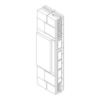
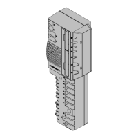
Fieldbus module EM3/2
7 Technical documentation
83296302 1/2018-01 La
12-32
7 Technical documentation
7.1 Profibus
7.1.1 Profibus output data to Fieldbus module
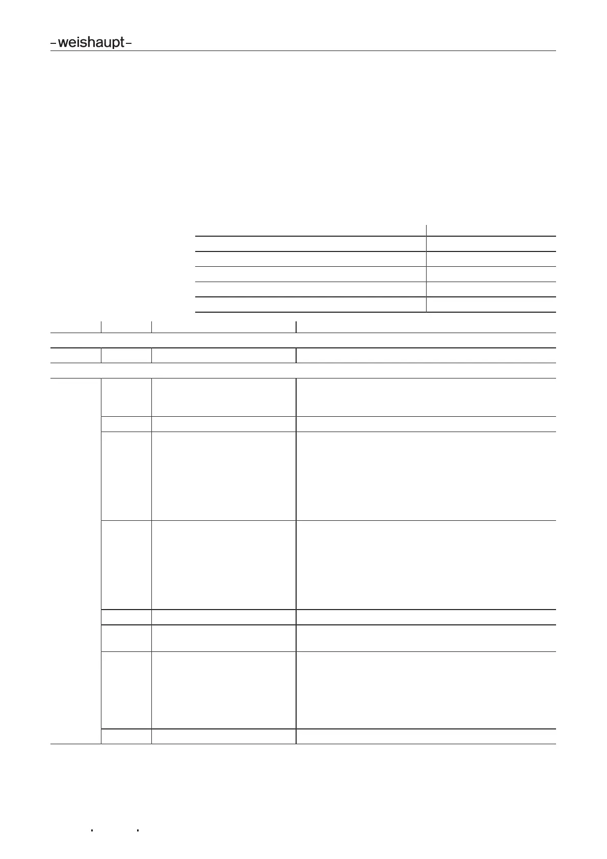
Five configurations (variables) of the output data can be selected from the GSD file.
Depending on the configuration, the output data is expanded by the corresponding
bytes. That means the B-Transfer is included in the C-Transfer, the C-Transfer is
included in the D-Transfer, etc.
Configuration Byte
A-Transfer –, no Bytes
B-Transfer AB0, AB1
C-Transfer AB0, AB1, AB2
D-Transfer AB0, AB1, AB2, AB3
E-Transfer AB0, AB1, AB2, AB3, AB4
Byte Bit Information Description
A-Transfer
– – no Bytes default –
from B-Transfer
AB0 0 Heat demand If the Bit is set to 1 by the master, a heat demand is
present until the heat demand is deactivated via Bit0 in
AB1.
1 not used –
2 Input Plus In control mode, the burner output can be increased via the
Bit. For each step, the signal must be applied for 500 ms
and removed again.
The step size can be changed in parameter72 via the
VisionBox Software.
In oil operation, the burner changes to or remains in stage
2.
3 Input Minus In control mode, the burner output can be decreased via
the Bit. For each step, the signal must be applied for 500
ms and removed again.
The step size can be changed in parameter72 via the
VisionBox Software.
In oil operation, the burner changes to or remains in stage
1.
4 not used –
5 OutputB4 switches (if para-
meter110 is set to 247)
Output B4 can be switched on and off. Prerequisite is that
parameter110 is configured to 247.
6 Remote reset (if parameter 269
set to 1)
If the Bit is set to 1 by the Master, and only reset to 0 after
0.5s, the combustion manager is reset.
If the Bit is held on 1 for more than 5s, the combustion
manager is not reset.
To be able to utilise Bus remote reset, parameter269 must
be set to 1.
7 not used –
 Loading...