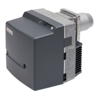
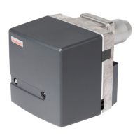
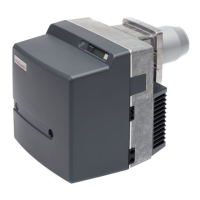
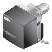
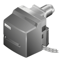
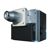
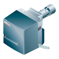
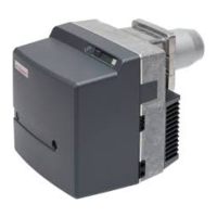
The Weishaupt WL20/1-C oil burner is a device designed for efficient and reliable combustion of oil, suitable for various heating applications. This manual provides comprehensive instructions for its installation, operation, and maintenance.
Function Description:
The oil burner's primary function is to atomize fuel oil and mix it with combustion air to create a combustible mixture, which is then ignited to produce heat. Key components contributing to this process include:
- Air damper: Regulates the air quantity required for combustion. It can be set manually or automatically closed by an actuator during burner shutdown.
- Fan wheel: Supplies combustion air from the air intake housing to the combustion head.
- Diffuser: Adjusts the mixing pressure and air quantity required for combustion by positioning the flame tube and diffuser.
- Oil pump: Draws oil through the supply line and carries it under pressure to the oil nozzle. A pressure regulating valve maintains constant oil pressure. A solenoid valve opens and closes the oil supply to the nozzle.
- Combustion Manager (W-FM): The control unit that monitors and controls the sequence of operation.
- Ignition unit: Creates a spark at the electrode to ignite the fuel/air mixture.
- Flame sensor: Monitors the flame signal. If the flame signal becomes too weak, the combustion manager initiates a controlled shutdown.
The burner's operation follows a specific sequence:
- Pre-purge without actuator: At heat demand, the burner starts after the initialisation time (Ti) has elapsed. The combustion chamber is pre-purged.
- Pre-purge with actuator (optional): At heat demand, the air damper actuator starts after the initialisation time (Ti) has elapsed. If the actuator limit switch (S2) is closed, the burner motor starts. The combustion chamber is pre-purged.
- Ignition: Ignition starts with the pre-purge time (Tv).
- Fuel release: Following the pre-purge time (Tv), the solenoid valve (K11) opens and releases the fuel.
- Safety time (Ts): With fuel release, safety time (Ts) and post-ignition time (TN2) start. The flame signal must be present within the safety time (Ts).
- Operation: The combustion manager monitors the flame signal via the flame sensor.
- Post-purge: If there is no longer a heat demand, the solenoid valve (K11) closes and stops the fuel supply. Post-purge time (TN) begins. Following the post-purge time (TN), the burner motor switches off. The actuator (optional) drives to the Closed position.
Important Technical Specifications:
- Type key: WL20/1-C (W: W burner, L: Fuel Oil EL, 20: Size, 1: Ratings size, C: Construction)
- Approval data: PIN 2014/68/EU: Z-IS-TAF-MUC-14-05-376456-004, DIN CERTCO: 5G982, Basic standards: EN 267:2011.
- Electrical data:
- Mains voltage / mains frequency: 230 V/50 Hz
- Consumption at start: max 452 W
- Consumption during operation: max 352 W
- Power consumption: max 2.2 A
- Internal unit fuse: T6.3H, IEC 127-2/5
- External fuse: max 16 AB
- Ambient conditions:
- Temperature in operation: -10°C ... +40°C
- Temperature during transport / storage: -20°C ... +70°C
- Relative humidity: max 80 %, no dew point
- Fuels: Fuel oil EL to DIN 51603-1, Fuel oil EL A,BS to DIN 51603-6, Fuel oil EL to ÖNORM-C1109 (Austria), Fuel oil EL to SN 181 160-2 (Switzerland).
- Emissions (NOx values): Influenced by combustion chamber dimensions, flue gas system, fuel, combustion air (temperature and humidity), and medium temperature.
- Sound levels:
- Measured sound power level LWA (re 1 pW): 70 dB(A)
- Uncertainty value KWA: 4 dB(A)
- Measured sound pressure level LpA (re 20 µPa): 65 dB(A)
- Uncertainty value KpA: 4 dB(A)
- Combustion heat rating: 50 ... 120 kW (4.2 ... 10.1 kg/h). The oil throughput data relates to a calorific value of 11.9 kWh/kg for fuel oil EL.
- Dimensions:
- Length: 393 mm
- Width: 358 mm
- Height: 376 mm
- Combustion head extension options: 100 mm, 200 mm, 300 mm.
- Weight: approx. 20 kg
- Oil supply:
- Suction resistance: max 0.4 bar
- Supply pressure: max 2 bar
- Supply temperature: max 60 °C
- Oil hose connection: G⅜
- Nominal pressure: 10 bar
- Thermal load: max 100 °C
Usage Features:
- Target group: The manual is intended for operators and qualified personnel. Work on the unit must only be carried out by personnel who have the relevant training and instruction.
- Safety measures: Safety-relevant fault conditions must be eliminated immediately. Components showing increased wear and tear or whose design lifespan is exceeded prior to the next service should be replaced as a precaution.
- Installation: Requires careful consideration of installation location, preparation of the heat exchanger, and proper burner installation. The burner can be rotated by 180° if space is limited.
- Nozzle selection: Recommended nozzles are specified (Steinen, Fluidics) with corresponding characteristics and burner capacity in kW at various pump pressures.
- Commissioning: Must be carried out by qualified personnel. Requires checking all assembly and installation work, sufficient combustion air, proper heat exchanger, correct setting and measuring devices, and proper flue gas ducts. Includes connecting measuring devices, setting diffuser and air damper, adjusting the burner, and concluding work with safety checks and combustion value recording.
- Operation: The illuminated push button on the combustion manager indicates operating conditions (orange for start phase, flashing orange for ignition and pre-purge, green for operation, red for fault).
Maintenance Features:
- Servicing: Servicing must only be carried out by qualified personnel. The combustion plant should be serviced annually. Depending on site conditions, more frequent checks may be required. Components with increased wear and tear or whose design lifespan is exceeded prior to the next service should be replaced as a precaution.
- Service plan: Provides criteria and design lifespan for various components (fan wheel, air duct, air damper, ignition cable, ignition electrode, combustion manager, flame sensor, flame tube/diffuser, oil nozzle, oil pump filter, oil hose, oil solenoid valve) and corresponding service procedures (clean, replace).
- Replacement procedures: Detailed instructions are provided for replacing components such as the nozzle, ignition electrodes, mixing head, air regulator, angle drive, oil pump, fan wheel, burner motor, oil pump filter, and fuse.
- Troubleshooting: A comprehensive section on troubleshooting provides fault codes, causes, and rectification steps for various issues, including burner not operating, illuminated push button off/red/flashing, oil pump supply issues, no ignition, solenoid valve not open, combustion manager issues, burner motor not running, no flame formation, flame signal issues, actuator limit switch issues, contact issues, and combustion manager faults.
- Operating problems: Addresses common operating problems such as poor start behavior, oil pump mechanical noise, oil nozzle atomisation, flame tube/diffuser soot deposit, combustion pulsating or booming, high CO content, stability problems, and restart after flame failure, along with their causes and rectification.