Do you have a question about the Weishaupt WL10/2-C Z and is the answer not in the manual?
Explains symbols like DANGER, ATTENTION, and numbered lists used in the manual.
Details contractor responsibilities for passing instructions to the plant operator and keeping them with the appliance.
Outlines conditions under which Weishaupt accepts no liability for damages or injury, such as improper use or alterations.
Covers dangers of improper use, personnel training, organisational measures, and informal safety practices.
Addresses electrical safety, maintenance procedures, equipment alterations, and environmental responsibility.
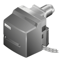
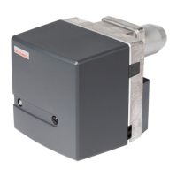
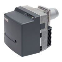
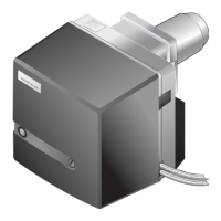
Lists suitable applications and conditions for the Weishaupt oil burner WL10, including fuel types and ambient limits.
Details burner parts like combustion manager, flame sensor, and the step-by-step operational sequence.
Lists technical data, setting procedures, priming, and hose details for the AT2 45C oil pump.
Emphasizes electrical isolation before installation to prevent electric shock and serious injury.
Covers checking delivery for completeness and damage, transport weight, and storage conditions.
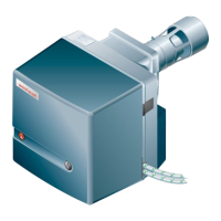
Discusses checking burner plate ratings against appliance specifications and space requirements.
Guides safe installation of the oil supply system, including pipe selection and filter installation.
Provides details on tank elevation, ring main operation, and pipeline length selection based on throughput.
Guides appliance preparation, installation steps, connecting oil hoses, and rotated mounting.
Covers checking plug polarity, wiring diagrams, and specific electrical isolation requirements for Austria.
Provides tables and examples for selecting the correct nozzle based on pressure and firing rate.
Emphasizes that initial commissioning must be performed by authorized personnel and safety equipment checked.
Covers venting the suction line, connecting instruments, and a comprehensive pre-start checklist.
Covers presetting diffuser and air damper values based on combustion chamber resistances.
Details air damper settings for full/partial load and the switch point for the full load solenoid valve.
Details the step-by-step operational sequence of the burner from demand to shutdown, including timings.
Presents the electrical wiring diagram for the WL10/2-C burner, detailing connections and components.
Details the functions of the W-FM 10 push button for operation, reset, and diagnostic code output.
Explains how to interpret signal lamp patterns and lists general fault causes and rectification steps.
Covers faults related to flame sensor, motor, ignition, oil pump, nozzle, and oil leaks.
Details faults related to combustion head, voltage supply, solenoid valves, and servomotor operation.
Addresses startup problems, pulsing, flame failure, and sensor issues, recommending combustion tests.
Emphasizes safety, qualified personnel, and preparation/completion steps for maintenance tasks.
Outlines the recommended annual servicing schedule and key function tests to perform.
Guides the process of removing, refitting, and handling burner nozzles, advising against cleaning.
Provides dimensions and instructions for setting ignition electrodes correctly to avoid contact with the spray cone.
Covers checking and adjusting mixing head settings and dimensions (S1/L) for optimal combustion.
Details procedures for removing and refitting the nozzle assembly and the housing cover.
Illustrates service position and procedures for servicing major components like the oil pump, fan motor, and fan wheel.
Covers cleaning the air regulator housing and air damper, and servicing the air damper angle gear.
Provides procedures for maintaining the oil pump filter and replacing the W-FM10 internal fuse.
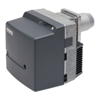
Details burner components, capacity graphs, permissible fuels, electrical data, and ambient operating conditions.
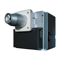
Presents detailed dimensional drawings, measurements, and the approximate weight of the burner.
Provides an example calculation for determining the CO2 setting value based on measured CO2.
Details the formula and parameters for calculating flue gas losses based on temperatures and CO2/O2 content.