Full load
Partial load
Full load (ST2) pre-setting:
Determine air damper setting using the full load curve in
the diagram and set full load limit switch (ST2) accordingly.
Partial load (ST1) pre-setting
Determine air damper setting using the partial load curve
in the diagram and set partial load auxiliary switch (ST1)
accordingly.
Pre-set switch point for the full load solenoid valve
(MV2):
Set the switch point to approx. 1/3 of the setting
movement between ST1 and ST2.
Example air damper setting WL10/2-C, vers. Z
Firing rate (Q
F
)
Full load pump pressure (22 bar): 57·1 kW
Partial load pump pressure (10bar): 38·1 kW
This results in an air damper setting
for full load (ST2) of: 33°
for partial load (ST1) of: 18°
Switch point for the full load solenoid valve (MV2)
33° (ST2) - 18° (ST1)
= 5°
3
+ air damper setting partial load (ST1) 18°
= switch point (MV2) 23°
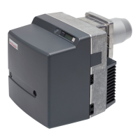
ST0 Limit switch closed
ST2 Limit switch full load
ST1 Auxiliary switch partial load
MV2 Auxiliary switch full load solenoid valve
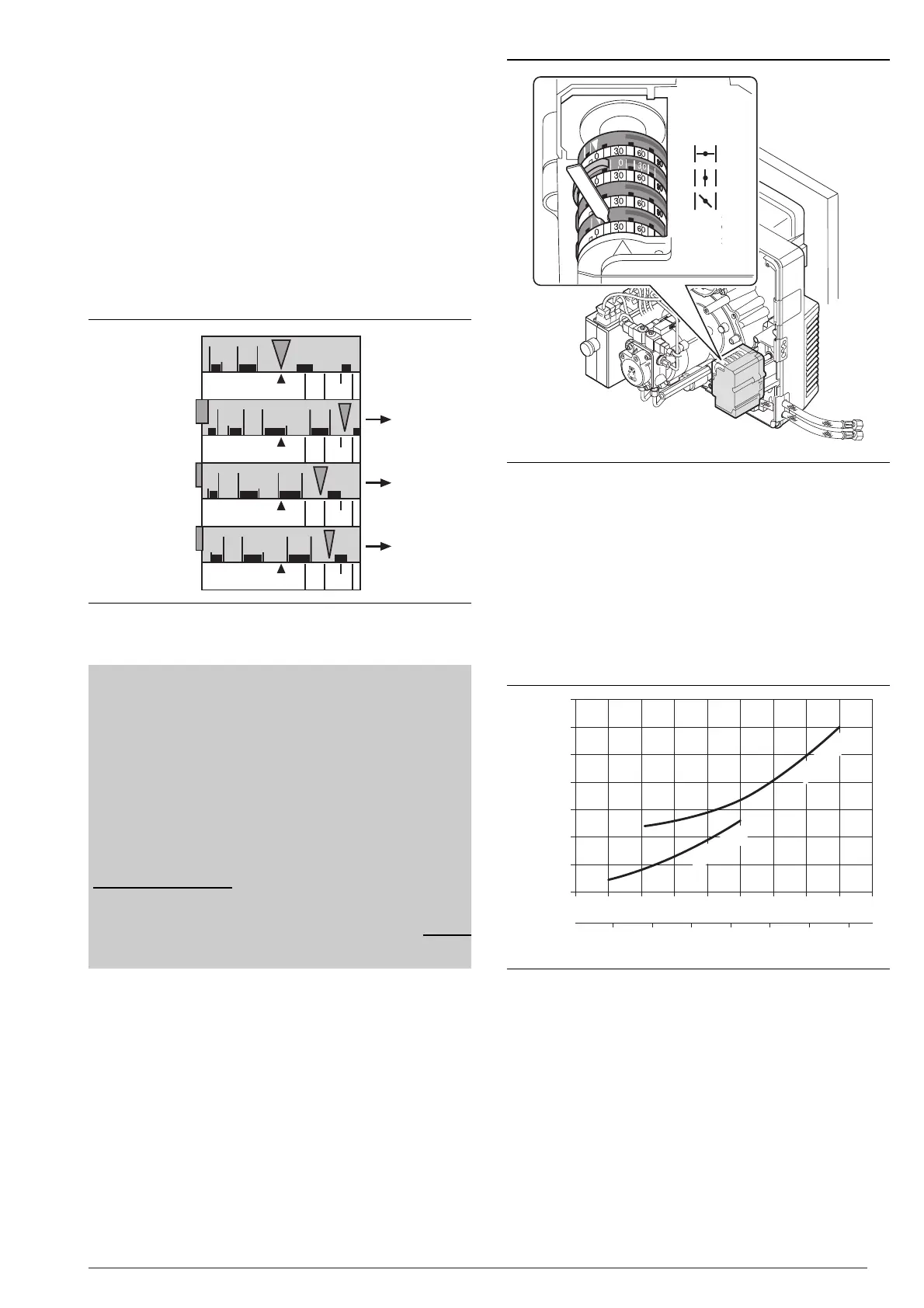
Set servomotor
 Loading...