C
Cynthia FergusonAug 20, 2025
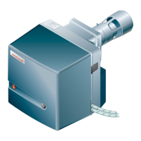
Why Weishaupt Burner motor does not run?
- RryanbennettAug 20, 2025
The burner motor might not be running due to several reasons: a lack of voltage, in which case you should check the voltage supply; a tripped overload relay or motor protection switch, so verify the setting; a defective motor contactor or frequency converter, suggesting a replacement; or a defective motor, which would also require replacement.