Do you have a question about the Weishaupt WL5/2-B and is the answer not in the manual?
The manual is intended for operators and qualified personnel, defining who should use it.
Explains safety symbols and general information symbols used throughout the manual.
Excludes warranty claims for damage due to non-approved application, improper use, or unauthorized modifications.
Specifies that the burner is suitable for EN 303 and EN 267 heat exchangers.
Outlines general safety measures and component replacement based on wear and lifespan.
Advises on safety precautions for electrical work, referencing DGUV Regulation 3 and EN 60900.
States that all modifications require written approval and prohibit fitting untested components or using non-original parts.
Discusses noise levels, potential hearing loss, and the use of protective equipment and sound attenuators.
Instructs to dispose of materials and components safely and environmentally friendly.
Explains the coding system for the burner type, fuel, size, rating, and construction.
Indicates the location of the serial number for identification and customer service.
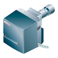
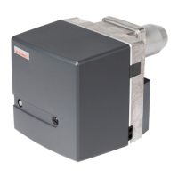
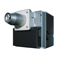
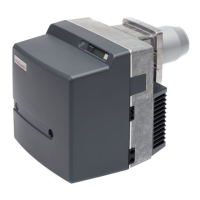
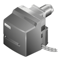
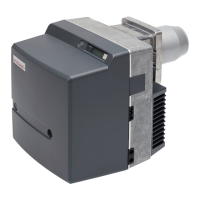
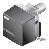
Details the operational functions of the burner's key components.
Details the function of the air damper, fan wheel, and diffuser in regulating combustion air.
Explains the operation of the oil pump, solenoid valve, and pressure regulating valve.
Describes the function of the combustion manager, burner motor, ignition unit, and flame sensor.
Outlines the step-by-step process from pre-purge to post-purge during burner operation.
Provides key technical specifications for the burner.
Lists approval certifications and basic standards like EN 267:2011.
Provides specifications for mains voltage, consumption, power, and fuses.
Specifies operating temperature, transport/storage temperature, and relative humidity limits.
Lists approved fuel oils according to various DIN, ÖNORM, and SN standards.
Details flue gas emissions (NOx) and sound levels (LWA, LpA) according to EN 267.
Presents combustion heat rating, oil throughput, and a capacity graph.
Shows detailed diagrams with measurements of the burner unit.
States the approximate weight of the burner.
Covers matching burner and heat exchanger, installation location, and preparing the heat exchanger.
Provides recommendations for nozzles and a table for selecting capacity based on pump pressure.
Details the steps for mounting the burner flange, gasket, and insulating material.
Explains the procedure for rotating the burner, including fitting a pressure hose and adjusting components.
Covers regulations, conditions for the oil pump and hoses, and connecting the oil supply.
Details safety precautions for electrical work and how to connect the plug.
Describes the illuminated push button on the combustion manager and its functions.
Explains the meaning of different illuminated push button colors and their corresponding operating conditions.
Lists essential conditions to be met before commissioning, including assembly, air supply, and safety devices.
Guides on connecting pressure measuring devices and ammeters for flame signal.
Instructs on setting the diffuser and air damper based on the capacity graph.
Shows a graph for setting the diffuser dimension based on combustion heat rating.
Presents a graph for setting the air damper based on combustion heat rating.
Details how to adjust the diffuser using a screw to achieve the required dimension.
Explains how to set the air damper using a setting screw or actuator.
Guides on finding the required mixing pressure from a diagram based on heat rating.
Covers checks during commissioning and steps for starting and adjusting the burner.
Lists final tasks after adjustment, including checking devices, entering data, and informing the operator.
Details procedures for determining excess air, flue gas temperature, and flue gas losses.
Provides instructions for switching off the burner and closing fuel shut-off devices for breaks.
Covers safety notes (electric shock, burns) and general servicing requirements.
Lists checks after servicing, including tightness, functions, combustion values, and refitting the cover.
Outlines components, their criteria/lifespan, and recommended service procedures (cleaning/replacement).
Describes how to place the burner into different service positions (A, B, C) for maintenance.
Provides step-by-step instructions for removing and fitting a new nozzle.
Explains how to position and adjust ignition electrodes relative to the nozzle.
Details the process of removing the mixing head, including unplugging cables and removing screws.
Covers setting the nozzle distance and basic settings of the mixing head components.
Guides on removing the air regulator, intake housing, and associated parts.
Provides instructions for removing and refitting the oil pump, including caution about connection.
Details the steps for removing and refitting the fan wheel, including alignment and grub screw.
Explains how to remove the burner motor after detaching other components.
Guides on removing and replacing the oil pump filter and gasket.
Details the procedure for replacing the fuse on the combustion manager.
Explains how the combustion manager indicates faults via the illuminated push button.
Lists common faults when the push button is off and their possible operator corrections.
Describes how to read error codes and reset the burner after a fault lockout.
Provides a table of fault codes, causes, and rectification steps for qualified personnel.
Lists error codes without lockout and their rectification by qualified personnel.
Lists common operating problems, their causes, and rectification steps.
Provides a table for converting pressure units between Bar, Pascal, hPa, kPa, and MPa.
Presents the electrical wiring diagram for the burner control system.
Covers regulations, general information, and suction resistance/supply pressure for oil supply.
Discusses anti-siphon valves, height differences, and system configurations for oil supply.
Covers damage due to incorrect connection and requirements for single pipe systems.
Mentions automatic venting of the oil pump in a two-pipe system.
Recommends ring main operation for multiple burners.