Do you have a question about the Weishaupt WG10 1-C Series and is the answer not in the manual?
Explains symbols and notes used in the instructions for clarity and safety.
Details responsibilities for passing operating instructions and required inspections.
Outlines conditions under which Weishaupt is not liable for damages or injuries.
Highlights risks associated with improper use of the equipment and required conditions for safe operation.
Specifies requirements for competent personnel handling installation, mounting, setting, and commissioning.
Emphasizes the use of protective clothing and regular checks of safety devices.
Stresses adherence to local codes and keeping safety notices legible.
Details precautions for safe operation, including regular checks of safety devices.
Provides critical steps to take in case of gas detection, including avoiding ignition sources and shutting off gas.
Outlines safety procedures for electrical work, including isolation and qualified personnel.
Specifies safety rules for maintenance, fault rectification, and handling of components.
Prohibits unauthorized alterations and requires manufacturer confirmation for any modifications.
Specifically prohibits alterations to the combustion chamber that hinder flame formation.
Advises on correct handling and disposal of materials with environmental consideration.
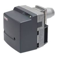
Details the intended applications and restrictions for the Weishaupt WG10 gas burner.
Explains the operational principles of the burner type, combustion manager, flame sensor, and servomotor.
Provides critical safety warnings regarding electrical isolation before starting installation work.
Details checks for delivery, guidelines for transport, and permissible storage conditions.
Covers checks for the burner nameplate and space requirements before assembly.
Provides step-by-step instructions for mounting the burner, including electrode checks.
Step-by-step guide for mounting the valve train assembly, including variations for rotation.
Procedure for testing the gas tightness of the valve train and its components.
Instructions for making the electrical connections to the burner and its components.
Emphasizes that initial commissioning must be done by authorized personnel and safety checks are crucial.
Details procedures for purging the gas supply line and checking gas supply pressure.
Instruction on connecting a manometer to measure gas pressure during commissioning.
Guides on selecting and setting pre-settings for air damper and diffuser based on heat rating.
Details on setting gas pressure and factory pre-setting for the pressure regulator.
Steps for pre-setting components and setting limit switches before commissioning.
Actions to take for poor start behaviour, including diffuser and gas quantity adjustments.
Procedure for performing a differential pressure measurement to set the air pressure switch.
Explains when valve proving is activated and its purpose in burner operation.
Provides a key to understand the symbols and components used in the basic wiring diagram.
Describes the functions of the W-FM 10 signal button, including resetting lockout and diagnostic code transfer.
Checks for basic operational requirements and procedures for resetting burner lockout, including diagnostic codes.
Table mapping signal lamp codes to causes and remedies for combustion manager faults.
Troubleshooting steps for faults related to the motor, air supply, gas, ignition, flame monitoring, and servomotor.
Crucial safety guidelines for performing maintenance and service work, emphasizing qualified personnel and electrical isolation.
Outlines service intervals, testing/cleaning tasks, and components requiring manufacturer-specific servicing.
Warnings regarding gas leaks, explosion risks during assembly, and burns from hot parts.
Step-by-step instructions for removing and refitting the mixing head, including seal integrity checks.
Explains how to put the fan housing cover in a service position for easier access to components.
Steps for removing and refitting the fan wheel and motor, and the servomotor and air damper drive.
Steps to remove and refit the gas butterfly valve and air regulator housing, including safety warnings.
Steps for replacing the coil and gas filter on the multifunction assembly, including safety and testing.
Procedure for replacing the internal fuse of the W-FM10 combustion manager.
Lists the specifications of the combustion manager, motor, servomotor, ignition unit, and pressure switches.
Presents capacity graphs showing combustion chamber pressure versus combustion heat rating.
Lists the types of fuels that are permissible for use with the burner.
Details electrical specifications such as mains voltage, consumption, and fusing.
Specifies the permitted temperature, humidity, and relevant guidelines for EMC and low voltage.
Table providing detailed dimensions of the burner in millimeters.
Provides diagrams, dimensions, and weight of the valve train components.
Explains how to calculate gas throughput for correct thermal input, including volume conversions.
Describes how to determine flue gas losses using oxygen or carbon dioxide content and temperatures.
Demonstrates a simplified calculation for the target CO2 value based on excess air and CO limit.