Start partial
load
21
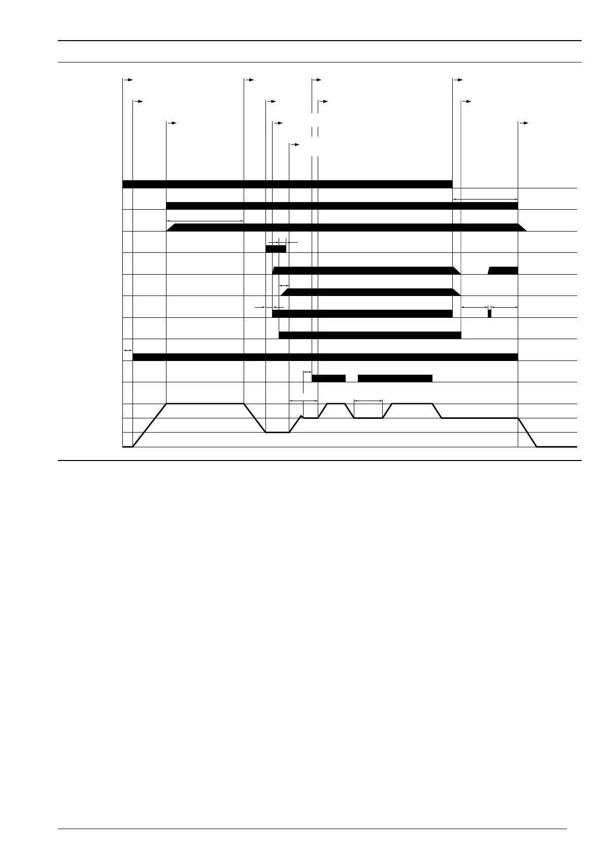
5.5 Sequence of operation and wiring diagram
Switch times
Start-up waiting time (test)T
W
3 secs.
Pre-purge time T
V
20 secs.
Pre-ignition time T
VZ
2 secs.
Post ignition time T
NZ
3·5 secs.
Safety time T
S
2·8 secs.
Residence time partial load T
VK
5 secs.
Flame stabilisation time T
F
2 secs.
Test time valve proving
Phase 1 T
P1
(1. valve) 9·3 secs.
Phase 2 T
P2
(2. valve) 9·7 secs.
Post purge time T
N
24 secs.
Servomotor run time in operation
full setting movement 0° - 90° approx. 3 secs.
Valve proving
Following a power cut, the low gas pressure programme
or a burner lockout, valve proving is activated at the
beginning of the next burner start.
Sequence of operation diagram
Boiler control
Burner motor
Air pressure
switch
Ignition unit
Gas pressure
switch
Flame signal
1st. valve
2nd. valve
(3rd. valve)
Ratings control
Servomotor
GL
KL
ZL
Zu
Ready for
operation
(Standby)
Air damper to
full load setting
Boiler control
ON
Pre-purge
Start ignition
load
Ignition
Gas valve
open
Release ratings
control
Start full
load
Boiler
control OFF
Valve proving
 Loading...