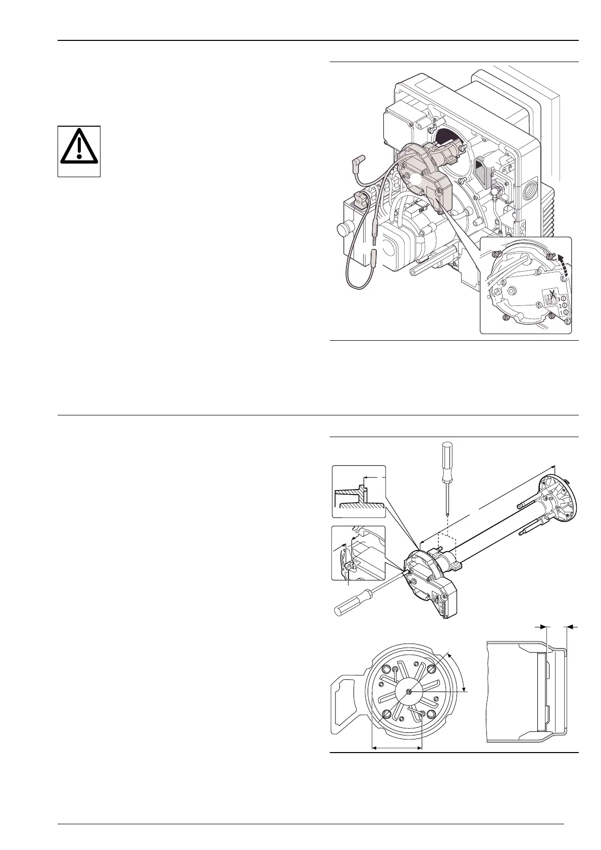
7.3 Mixing head - removal and refitting
Removing
1. Remove the flame sensor or ionisation plug ➂
2. Remove the ignition cable ➀ from the ignition unit
3. Loosen screws ➃
4. Remove mixing head ➁ from the housing (lightly rotate)
Refitting
Danger of explosion!
Misalignment of the seal ➄ can result in a gas
leak during burner operation.
When refitting the mixing head ensure the gas
seal is clean and aligned correctly. Replace it if
necessary. When commissioning the burner
check the seal is sound with a leak detector.
To refit, reassemble in the reverse order.
Removal and refitting the mixing head
➀ Ignition cable
➁ Mixing head
➂ Flame sensor
➃ Kombi-Torx screw
➄ Gas gasket
7.4 Mixing head setting
The distance between the diffuser disc and the edge of the
flame tube (dimension S
1
) cannot be measured whilst it is
mounted. To check, remove the mixing head and measure
dimension L.
1. Remove the mixing head (see Ch. 7.3.)
2. Turn the setting screw ➀ until it is level with the mixing
chamber housing (scale setting “0” or dimension X =
0).
3. Loosen screws ➁.
4. After setting dimension L, fix the collar ➂ with the lock
nuts ➁.
Setting dimensions
Dimension X _____________________________ 0 mm
Dimension L _____________________________ 278 mm
Dimension S1 _____________________________ 10 mm
Note: After loosening the lock nut check position of
electrodes and gas drillings (control dimension
K).
Control dimension K _______________________ 62·5 mm
Setting the mixing head
 Loading...