4.4 Burner installation
Preparing the heat exchanger
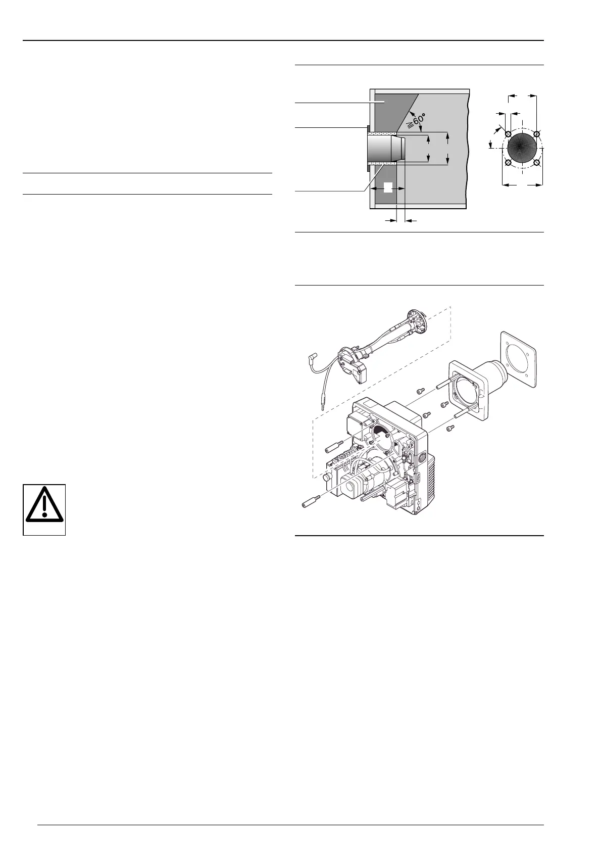
The diagram shows the refractory for a heating appliance
without cooled front. The refractory can, however, take a
conical shape (≥ 60°). Refractory may not be required on
boilers with water-cooled fronts, unless the manufacturer
gives other instructions. The front edge of the combustion
head should, as a minimum be flush with the refractory, or
protrude a maximum of 30mm.
Comb. Dims in mm
head d
1 d2 d3 d4 d5 l1
WG10-C 120 M8 150-170 130 135 140
** Depending on type of heat exchanger.
See manufacturers information!
The gap between
combustion head
and refractory must
be filled with
resilient, non-
combustible
insulating material.
Do not make solid.
Heat exchanger
drilling dims.
Refractory
Flange gasket
Refractory and drilling dimensions
Burner installationBurner mounting
1. Remove mixing head ➄ (see Ch. 7.3)
2. Remove screws ➃.
3. Separate burner flange ➁ with flame tube from housing.
4. Fix burner flange with screws ➂ to the boiler plate.
5. Place burner housing onto stay bolts ➅.
6. Fit screws ➃ and tighten.
7. Check setting of ignition and ionisation electrodes (see
Ch. 7.5).
8. Refit mixing head (see Ch. 7.3)
Ensuring that the gas-canal gasket is located correctly.
Fitting burner rotated by 180°
For valve trains fitted from the left, the burner can be
rotated by 180°. No other conversion work is required.
➀ Flange gasket
➁ Burner flange
➂ Hexagonal screw
➃ Hexagonal screw
➄ Mixing head
➅ Stay bolt
Danger of getting burnt
Some burner parts (e.g. flame tube, burner
flange, etc.) become hot during burner
operation and should be allowed to cool prior
to service work being carried out.
 Loading...