11
4.5 Valve train installation
Risk of explosion!
Gas leaks can lead to the build-up of explosive
gas/air mixtures. With the presence of an
ignition source, these then result in
explosions.
To avoid accidents, please follow the following safety
instructions on valve train installation.
☞ Before beginning work, close all the relevant shut off
devices and ensure they cannot be accidentally
reopened.
☞ Ensure the valve train components are correctly
aligned and that all the joints are clean.
☞ Flange seals must be fitted correctly on the machined
faces.
☞ Tighten screws evenly diagonally opposite.
☞ Valve trains must be mounted tension-free.
Do not compensate for misalignment by over-
tightening.
Do not tighten or seal pipe thread connections while
mounted on the burner.
☞ The valve trains must be fixed and supported securely.
They must not be allowed to vibrate during operation.
Supports suitable for the site should be fitted during
installation.
☞ Only sealing agents tested and approved by the gas
supplier must be used.
The double nipples supplied have already been coated
with an approved substance.
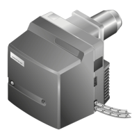
Mounting the valve train from the right
1. Remove the protective film from the gas connection
flange.
2. Mount the components, pre-assembled, in the order
shown in the diagram.
Note W-MF: Can be mounted in horizontal or
vertical pipework.
Installation example
➀ Double nipple
➁ Multifunction assembly W-MF
507
➂ Elbow
➃ Ball valve with flange
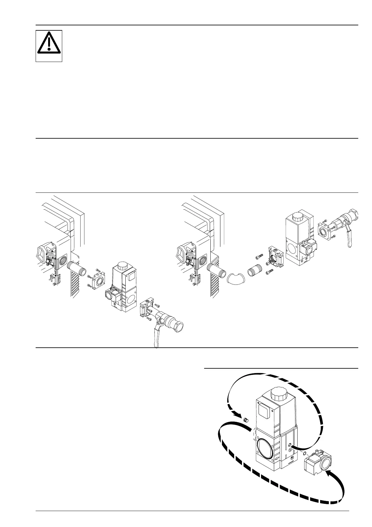
Mounting the valve train from the left
With the burner rotated through 180°, the valve train as
described above can be fitted from the left.
However, the following measures are required.
1. Prior to mounting the multifunction assembly:
Remove gas pressure switch ➂.
2. Remove closing plug ➀.
3. Fit gas pressure switch on opposite side. Pay attention
when fitting the O ring ➁!
4. Refit closing plug on opposite site.
 Loading...