7
3 Technical description
3.1 Permissible applications
3.2 Function
The Weishaupt WG10 gas burner is suitable for:
• mounting on heat exchangers according to EN303-3
or DIN4702-1
• on warm water plant with intermittent or continuous
operation (combustion manager will switch off once
during 24h)
Any other use is only permissible with the written
agreement of Max Weishaupt GmbH.
• The burner must only be operated with the type of gas
given on the burner plate.
• The burner must only be operated under the
permissible ambient conditions (see Ch. 8.5)
• The burner must not be used outside. It is only suited
for operation inside.
• The burner must not be used outside of its capacity
range (see capacity graphs, Ch. 8.2).
• The gas supply pressure must not exceed the gas
pressure given on the burner plate.
Burner type
Forced draught gas burner for single-stage or two-stage
operation.
• single stage: ignition load ➱ full load via 4 pole
connection plug (supplied loose, fitted with plug-link
(1) as per wiring diagram).
• two stage: ignition load ➱ partial load ➱ full load via 4
pole plug from heat exchanger.
Combustion manager (W-FM 10)
Main points:
• Safety via internal fuse
• Control and monitoring of all burner functions
• Safety via two microprocessors (reciprocal monitoring)
• Data bus connection (eBUS)
• Signal lamp to show operational status:
Green Burner operating
Flashing green Burner operating with weak
ionisation current
Orange Burner start, internal test
Flashing orange Ignition phase
Red Burner lockout
Flashing orange / red Low voltage or internal safety
fault
Flashing green / red Flame-Simulation
flashing red / orange, Over-voltage
short pause
Flashing red Low gas
Servomotor
A servomotor on the air damper controls the gas/air ratio
via mechanical compound with the gas butterfly valve
Multifunction assembly W-MF
with the following functions:
• Pressure regulator
Ensures a constant gas pressure to the burner,
negating the affects of gas pressure variations of the
gas supply main. The control pressure is commissioned
with the setting screw.
• 2 Solenoid valves (class A)
• Gas filter
• Gas pressure switch
If the gas pressure is insufficient the low gas
programme is initiated. The gas pressure switch is also
employed for automatic valve proving.
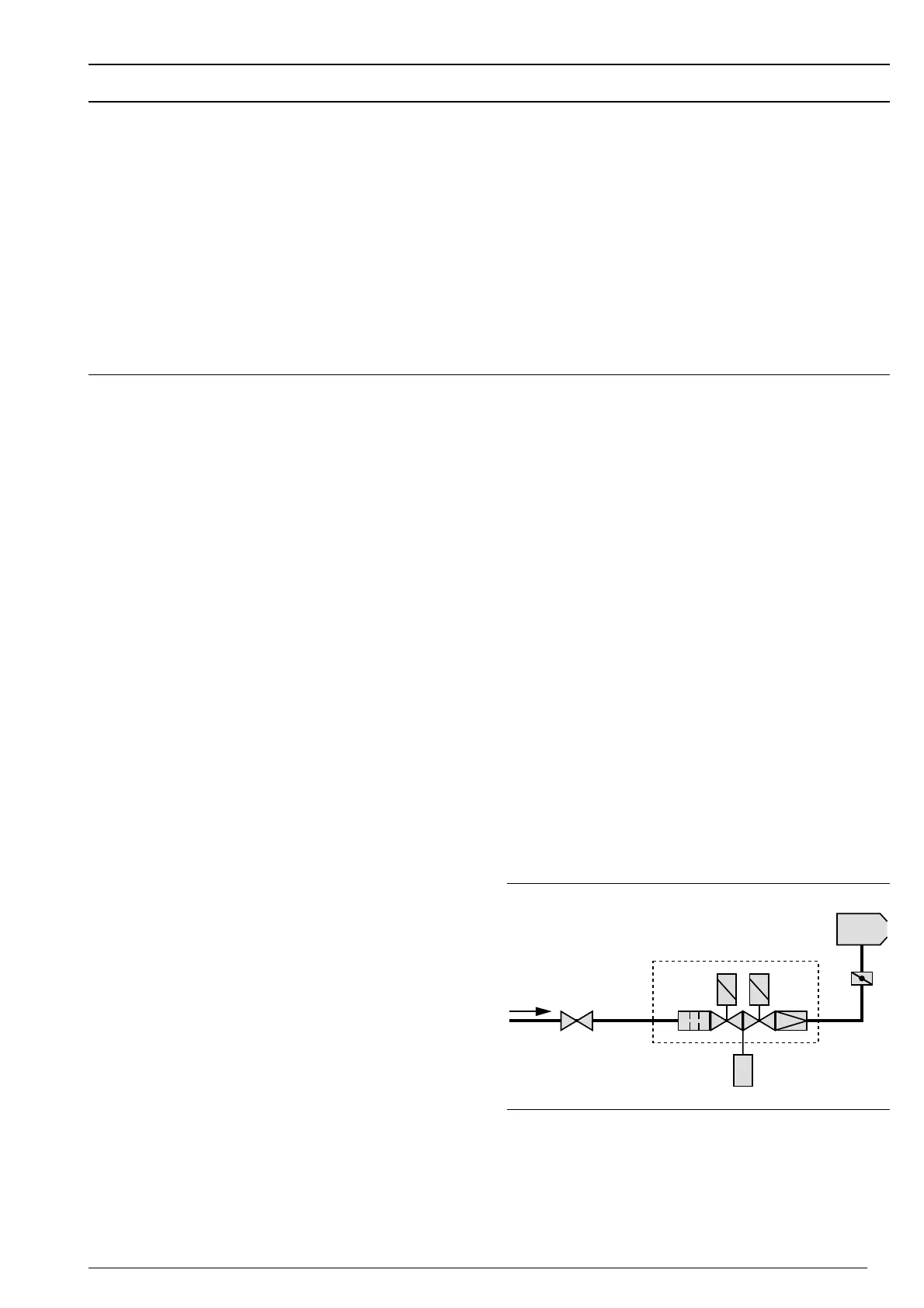
➀ Ball valve with thermal
shut off device
➁ Multifunction assembly
➂ Gas butterfly valve
➃ Burner
Flame sensor
Monitors the flame during all phases of operation. If the
flame signal does not correspond to the sequence of
operations, a safety lockout will occur.
Air pressure switch
If the air supply fails the air pressure switch activates a
safety shutdown.
Sequence of operations
Demand for heat from the appliance controller:
• Servomotor function is tested
• Fan start - prepurge of the combustion chamber
• Ignition on
• Solenoid valves open - fuel release
• Flame formation
• Depending on heat demand the air damper and gas
butterfly open in compound
• After 24 hrs. continuous operation a controlled
shutdown and restart is activated.
Sufficient heat attained:
• Solenoid valves close
• Post-purge of the combustion chamber
• Valve proving of solenoid valves
• Burner switches off to Standby
Schematic of gas valve trains
 Loading...