22
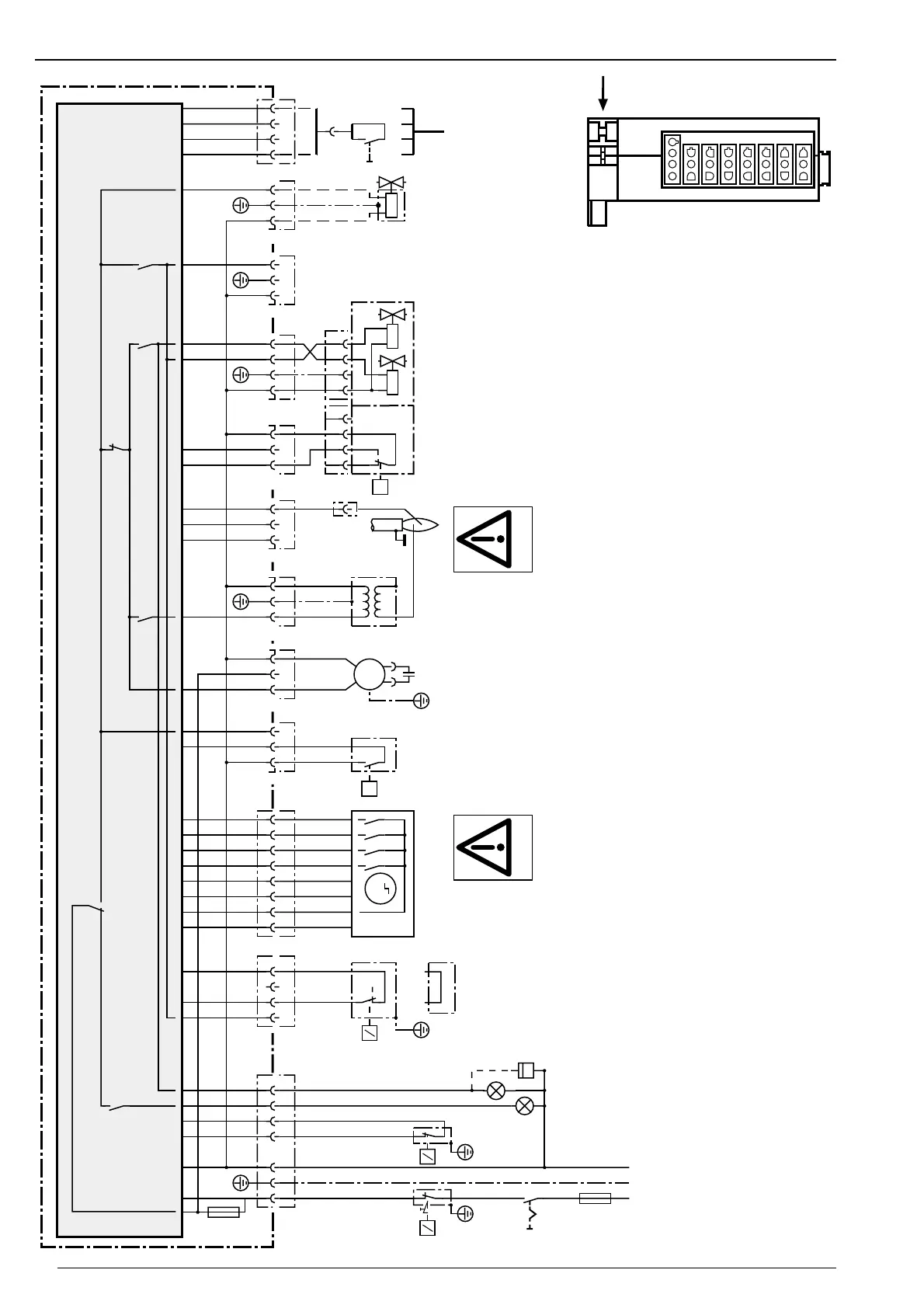
Basic wiring diagram
Air/Gas
Legend:
A1 Combustion manager with plug connectors
B1 Flame sensor
C1 Motor capacitor
F1 External fusing (max. 16 A)
F2 Temperature / pressure limit controller
F3 Temperature / pressure controller
F4 Temperature / pressure controller full load
F7 Internal fuse 6.3A
F10 Air pressure switch
F11 Low gas pressure switch
H1 Fault lamp-remote
H2 Operation lamp-remote
M1 Burner motor
P1 Hours counter (optional)
S1 Main switch
S2 Remote reset (optional)
T1 Ignition unit
X3 Plug console
X4 Printed circuit boards - direct plug (servomotor)
X5 Printed circuit boards - direct plug (Bus/S2)
X6,X7 Burner connection plugs
➀ Linked-plug X7 for single stage operation
X8 Plug flame sensor
X9 Plug double solenoid valve
Y2 Double solenoid valve
Y4 External valve (liquid petroleum gas)
Y20 Servomotor
➀
Combustion managers
are safety devices.
Do not open!
 Loading...