Function test
1. Open ball valve and close again for sequence test with
ball valve closed.
2. Switch on burner. Burner starts in line with the
sequence of operation.
3. The gas pressure switch detects insufficient gas. The
combustion manager goes to the low gas programme
(flashing red).
4. Reset low gas programme by pressing the reset-
button.
Commissioning
❏ Presetting of diffuser, air damper, multifunction
assembly must have been carried out.
❏ Ignition (ZL) and partial load (ST1) switches must be
set to 5° (factory setting).
❏ Set full load limit switch (ST2) to previously calculated
value.
Danger of explosion!
CO build-up due to incorrect setting of the
burner. Check CO levels and when there is a
CO reading above desired value optimise
combustion. CO should not exceed 50 ppm.
Single stage operation:
1. Remove 4 pole connection plug (with bridge as per
wiring diagram)
2. Open gas ball valve and switch on burner.
3. Pre-purge starts in full load position.
4. Following pre-purge the servomotor goes to ignition
load.
5. Flame formation following valve proving.
6. Set setting pressure to table value.
7. Plug in 4 pole connection plug
➭ burner runs to full load.
8. Carry out combustion control (see appendix) and gas
throughput measurement.
9. Correct gas quantity by adjusting gas setting pressure.
10.Correct excess air by adjusting air damper and diffuser
setting.
11.Remove connection plug again ➭ burner goes to
ignition load, carry out combustion control and set
excess air (see table Setting values ignition load) by
adjusting the gas quantity at setting screw 1.
12.Plug in connection plug (4 pole).
18
Two stage operation:
1. Remove 4 pole connection plug and replace with plug
switch (order No. 130 103 1501/2)
2. Open gas ball valve and switch on burner.
3. Pre-purge starts in full load position.
4. Following pre-purge the servomotor goes to ignition
load.
5. Flame formation following valve proving.
6. Set setting pressure to table value.
7. Drive to full load via plug switch.
8. Carry out combustion analysis (see appendix) and gas
throughput measurement.
9. Correct gas quantity by adjusting gas setting pressure.
10.Correct excess air by adjusting air damper and diffuser
setting.
11.Drive to ignition load via plug switch, carry out
combustion control and set excess air (see table
Setting values ignition load) by adjusting the gas
quantity at setting screw 1.
12.Set partial load at limit switch ST1 whilst observing the
instructions given by the manufacturer and carry out
combustion analysis.
Set excess air at setting screw 2.
Correct gas throughput by adjusting limit switch (ST1).
13.Plug in connection plug (4 pole).
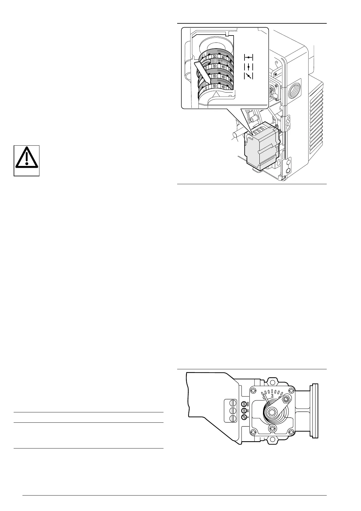
Setting the limit switch
Setting values ignition load
Gas type CO
2
O
2
Nat. Gas LL 8·8 - 9·3% 5 -4%
Nat. Gas E 9·0 - 9·5% 5 -4%
LPG 10·3 - 11·0% 5 -4%
Setting screw gas butterfly valve
Factory pre-setting:
ST0 : __________ 0°
ST2 : _________ 60°
ST1 : __________ 5°
ZL : __________ 5°
Effective range of setting screws:
Screw 3 :________________ 50° to 80°
Screw 2 :________________ 20° to 50°
Screw 1 : _________________ 0° to 20°
Factory settings: 3 turns OPEN
Note After adjusting a limit switch, its new switch
point has to be restarted.
On single stage operation this is done with the
4 pole connection plug, on two stage
operation with the commissioning plug switch.
MV2 Oil
 Loading...