Installation and operating instruction
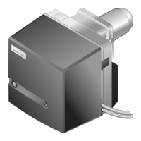
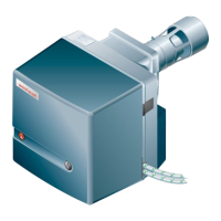
Oil burner WM-L20/2-A R (W-FM100/200)
15 Key word index
83252902 1/2019-09 La
81-84
15 Key word index
A
ABE........................................................................................12
Actuator......................................................................... 51, 54
Adjustment ...........................................................................36
Air damper ................................................................9, 21, 53
Air damper setting ..............................................................21
Air inlet mesh .......................................................................53
Air number ............................................................................43
Air regulator.................................................................. 52, 53
Ambient conditions.............................................................15
Aperture ........................................................................ 19, 26
Approval data.......................................................................13
Atomising pressure..................................................... 20, 37
B
Backup ..................................................................................40
Bar..........................................................................................62
Boiler room.............................................................................6
Breaks in operation.............................................................45
Burner control......................................................................14
Burner motor................................................................ 12, 14
C
Capacity................................................................................16
Capacity graph....................................................................16
CO content ..........................................................................43
Combustion air ...................................................................... 6
Combustion chamber pressure.......................................16
Combustion control............................................................43
Combustion head ...............................................................26
Combustion head extension..............................17, 19, 24
Combustion heat rating............................................. 16, 21
Combustion limit .................................................................43
Combustion Manager ........................................................12
Commissioning....................................................................33
Consumption........................................................................14
Continuous operation .......................................................... 6
Conversion table.................................................................62
Coupling................................................................................54
D
Data backup.........................................................................40
Design lifespan...............................................................6, 46
Dimension E .........................................................................21
Dimension S1 ......................................................................21
Dimensions...........................................................................17
Display...................................................................................32
Display and operating unit ................................. 12, 32, 57
Disposal .................................................................................. 7
Drilling diagram....................................................................19
Ducted air intake ............................................................6, 16
E
Electrical connection..........................................................30
Electrical data ......................................................................14
Electrodes.............................................................................49
Emission................................................................................15
Emission class .....................................................................15
Excess air..............................................................................43
Exchanging the unit............................................................59
Extension...............................................................................24
F
Fabrication number............................................................... 8
Fan pressure ........................................................................34
Fan wheel.........................................................................9, 56
Fault ............................................................................... 58, 60
Filter .......................................................................................63
Flame sensor........................................................................12
Flame signal .........................................................................12
Flame tube.......................................................................9, 19
Flame tube length ...............................................................24
Flame tube setting ...................................................... 21, 24
Flow pressure ......................................................................28
Flow temperature................................................................28
Flue gas losses....................................................................43
Flue gas measurement.......................................................43
Flue gas system...................................................................64
Flue gas temperature .........................................................43
Frequency converter ..........................................................12
Fuel.........................................................................................15
Fuel oil ...................................................................................15
Full load.................................................................................38
Fusing ....................................................................................14
G
Gas/air separator................................................................64
Guarantee............................................................................... 5
H
Heat exchanger ...................................................................19
Humidity ................................................................................15
I
Ignition electrode ................................................................49
Ignition electrodes ..............................................................49
Ignition position ...................................................................36
Ignition unit ...........................................................................12
Installation.............................................................................19
Installation elevation ................................................... 15, 16
Installation location.............................................................19
L
Liability..................................................................................... 5
Lifespan............................................................................6, 46
Limit switch...........................................................................12
Load distribution .................................................................44
Lockout...................................................................57, 58, 60
M
Mains voltage.......................................................................14
Max. oil pressure switch............................................ 10, 41
mbar .......................................................................................62
Measuring device................................................................34
Metering slot ........................................................................10
Min. oil pressure switch............................................. 10, 41
Mixing head .....................................................................9, 21
 Loading...