Installation and operating instruction
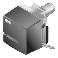
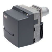
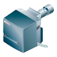
Oil burner WM-L20/2-A R (W-FM100/200)
4 Installation
83252902 1/2019-09 La
21-84
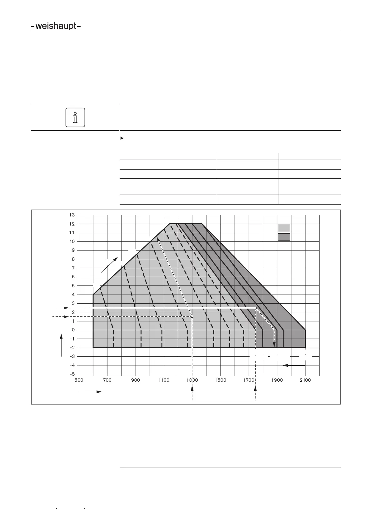
4.3 Set mixing head
4.3.1 Setting diagram
Set mixing head relative to the combustion heat rating required. Therefore the flame
tube setting and air damper setting are matched.
Do not operate the burner outside of the capacity graph.
Determine the required flame tube setting (dimension S1) and air damper setting
from diagram and note down.
Example1 Example2
Burner rating required 1300kW 1750kW
Combustion chamber pressure 1.5mbar 2.5mbar
Flame tube setting dimensionS1
(auxiliary dimensionE)
123mm
(10mm)
114mm
(19mm)
Air damper setting 55° > 90°
2
1
6
5
3
20°
30°
40°
50°
60°
118
(15)
108
(25)
113
(20)
103
(30)
70°
80°
4
1 Combustion heat rating [kW]
2 Combustion chamber pressure [mbar]
3 Air damper setting in degree of angle
(1
4 Flame tube setting dimension S1 [mm]
(1
(auxiliary dimension E [mm])
(1
5 Setting range of air dampers with flame tube setting CLOSED (123 mm)
6 Setting range for flame tube with air damper setting > 90°
(1
Different settings may be required depending on site conditions.
 Loading...