Installation and operating instruction
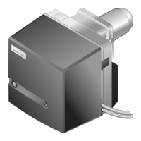
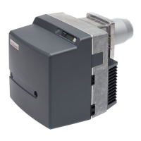
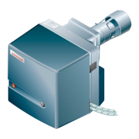
Oil burner WM-L20/2-A R (W-FM100/200)
4 Installation
83252902 1/2019-09 La
19-84
4 Installation
4.1 Installation conditions
Burner type and capacity graph
Burner and heat exchanger must be matched.
Check burner type and burner capacity.
Installation location
Prior to installation ensure that:
the space for the burner hinging range is sufficient [ch.3.4.7],
sufficient combustion air is available, if necessary install ducted air intake,
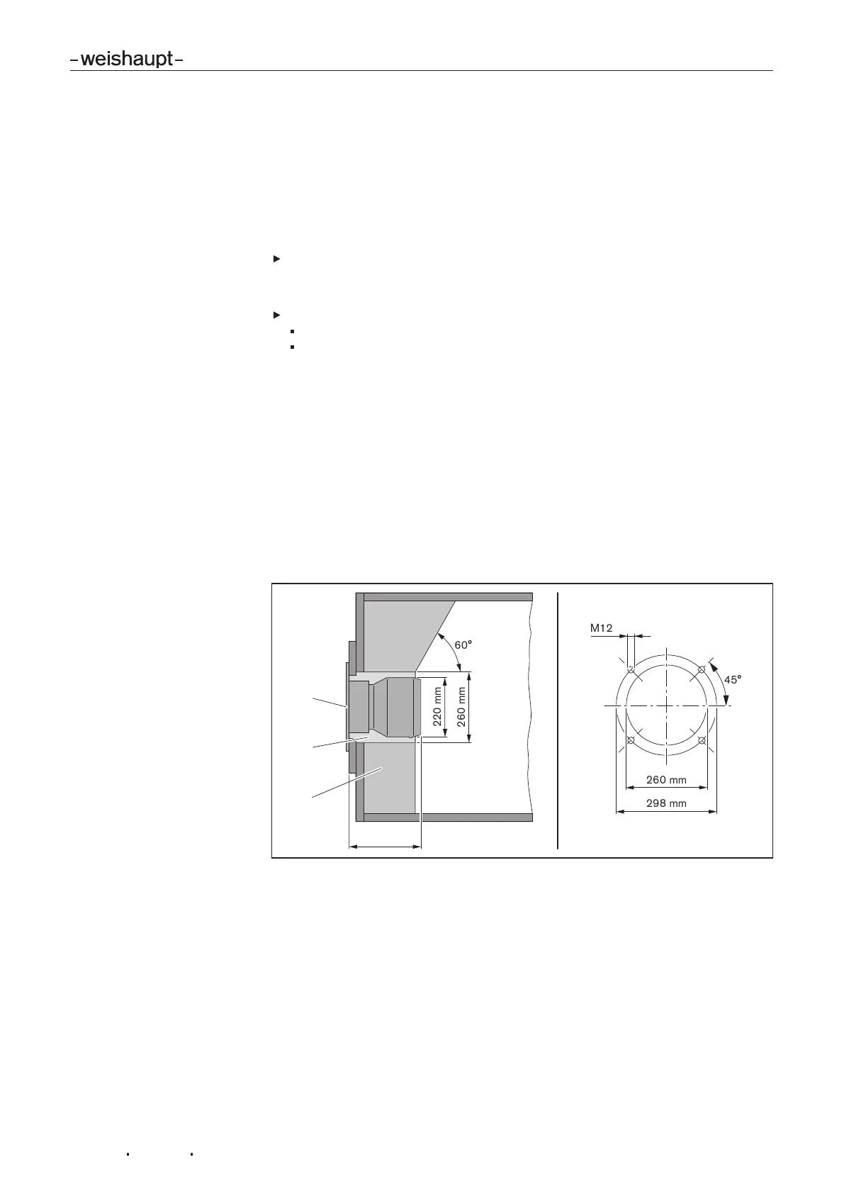
Prepare heat exchanger
The refractory3 must not protrude beyond the front edge of the combustion head.
The refractory can take a conical shape (min60°).
Refractory may not be required on boilers with water-cooled front, unless the man-
ufacturer gives other instructions.
Following installation, the aperture 4 between flame tube and refractory should be
filled with flame-proof, resilient insulating material. Do not make solid.
Heat exchangers with deep refractories or thick doors, or heat exchangers with re-
verse flame combustion chambers may require a combustion head extension. Head
extensions of 100, 200 and 300mm are available. Dimension 2 then changes ac-
cording to the head extension used.
The burner has to be hinged open by approx.70…80° to allow removal of the mix-
ing head.
1 Flange gasket
2 min 227 mm (combustion head OPEN)
max 247 mm (combustion head CLOSED)
3 Refractory
4 Aperture
 Loading...