Installation and operating instruction
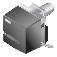
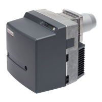
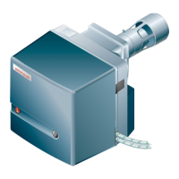
Oil burner WM-L20/2-A R (W-FM100/200)
4 Installation
83252902 1/2019-09 La
24-84
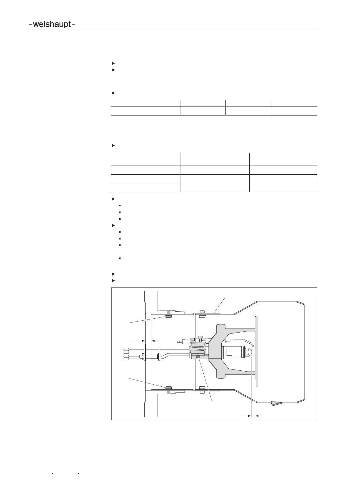
4.3.3 Set mixing head with combustion head extension
Hinge open the burner [ch.9.3].
Remove nozzle assembly.
1. Check flame tube length
Check total length of flame tube, see table.
Extension 100 mm 200 mm 300 mm
Total length 349 mm ±1 449 mm ±1 549 mm ±1
2. Nozzle distance and flame tube setting
The nozzle distance and the flame tube setting must be matched to one another.
Check nozzle distance, see table.
Nozzle distance (dimen-
sion A)
Flame tube setting4
7 mm 11 mm
10 mm 14 mm Factory setting
13 mm 17 mm
If necessary set nozzle distance:
Undo locking screws3.
Adjust diffuser and set nozzle distance(dimensionA).
Re-tighten locking screws.Re-tighten locking screws.
Match flame tube setting to nozzle distance:
Undo screws1.
Adjust flame tube 2, until flame tube setting 4 has been reached.
Centralise flame tube whilst checking the distance at a minimum of 3posi-
tions (each offset by 120°).
Re-tighten screws.
After every alteration to the nozzle distance or to the flame tube setting:
Check distance flame tube to diffuser.
Set ignition electrodes [ch.9.4]
 Loading...