Installation and operating instruction
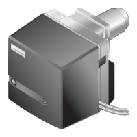
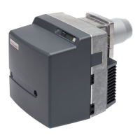
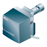
Oil burner WM-L20/2-A R (W-FM100/200)
4 Installation
83252902 1/2019-09 La
23-84
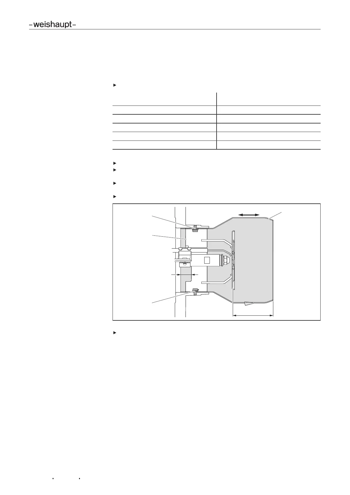
3. Set distance flame tube to diffuser
The distance of flame tube to diffuser (dimension S1) determined from the setting
diagram is set between the flame tube and diffuser sleeve using auxiliary dimension
E.
Measure auxiliary dimension E and compare to the table below.
Distance determined
Flame tube to diffuser (dimension S1)
Auxiliary dimension E
123 mm 10 mm (combustion head CLOSED)
118 mm 15 mm
113 mm 20 mm
108 mm 25 mm
103 mm 30 mm (combustion head OPEN)
If the distance varies from the measured value by more than 5mm, set flame tube:
Undo screws 1.
Adjust flame tube2 until auxiliary dimension E has been reached, ensuring not
to alter the setting of the diffuser sleeve3.
Centralise flame tube whilst checking the distance at a minimum of 3 positions
(each offset by 120°).
Re-tighten screws.
Set ignition electrodes [ch.9.4]
 Loading...